

Content last revised on September 26, 2026
Flashlight Dark Shadow Optical Diagnostic to Isolate Logic Versus Backlight Fault Modes
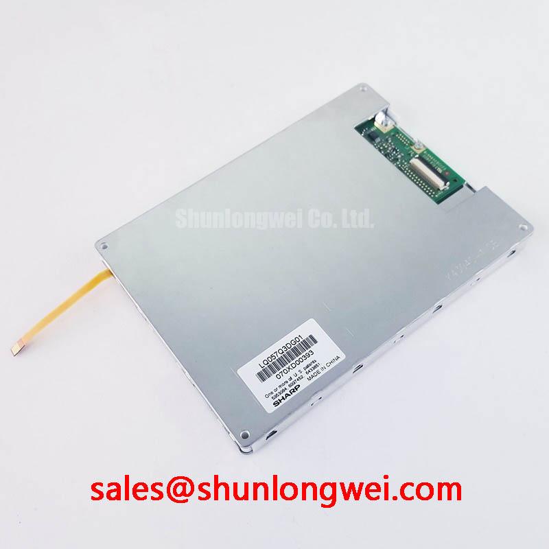
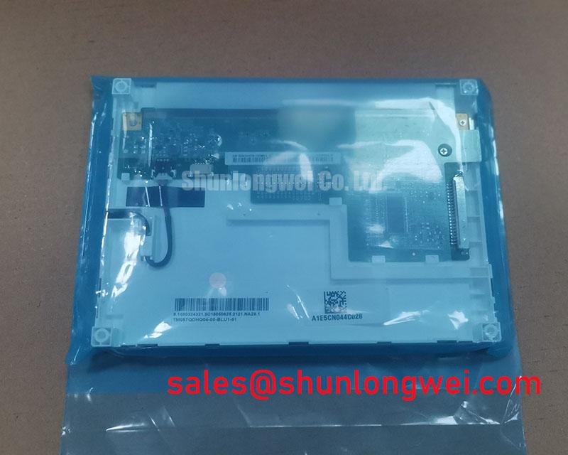
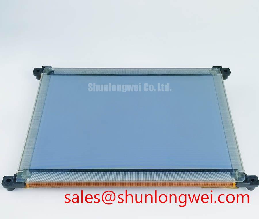
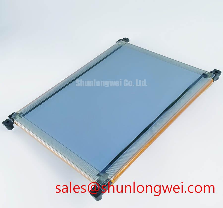
When a repaired control panel appears dark, first confirm whether image data is reaching the display before treating the symptom as a complete panel failure. Apply a known good test image or primary color sequence through the original controller, then inspect the surface under normal room lighting. A flashlight held at an oblique angle can reveal a faint image when the display logic is operating but the illumination path is inactive. This method is a practical diagnostic aid, not a panel specific acceptance limit.
Repeat the check with red, green, blue, white, and black images while observing for missing columns, horizontal bands, unstable areas, or color regions that do not follow the test pattern. A visible image with consistent geometry may direct the investigation toward the backlight supply, inverter, LED current path, or enable and dimming signals. Irregular line defects may also involve the panel drive region, connector contact quality, flex bonding, or signal integrity. These observations should be compared with a known good signal path rather than assigned to one internal cause without measurement.
The supplied factory information does not specify an LED half life, CCFL operating life, brightness decay curve, or a 50 percent luminance point for the LJ64ZU52. Such values must not be inferred from a generic TFT display category. If a maintenance record refers to a long operating life, the engineer should request the applicable Sharp documentation and confirm the driver conditions, ambient temperature, and brightness setting used for that claim.
High Voltage Striking Potential and Secondary Coil Insulation Testing
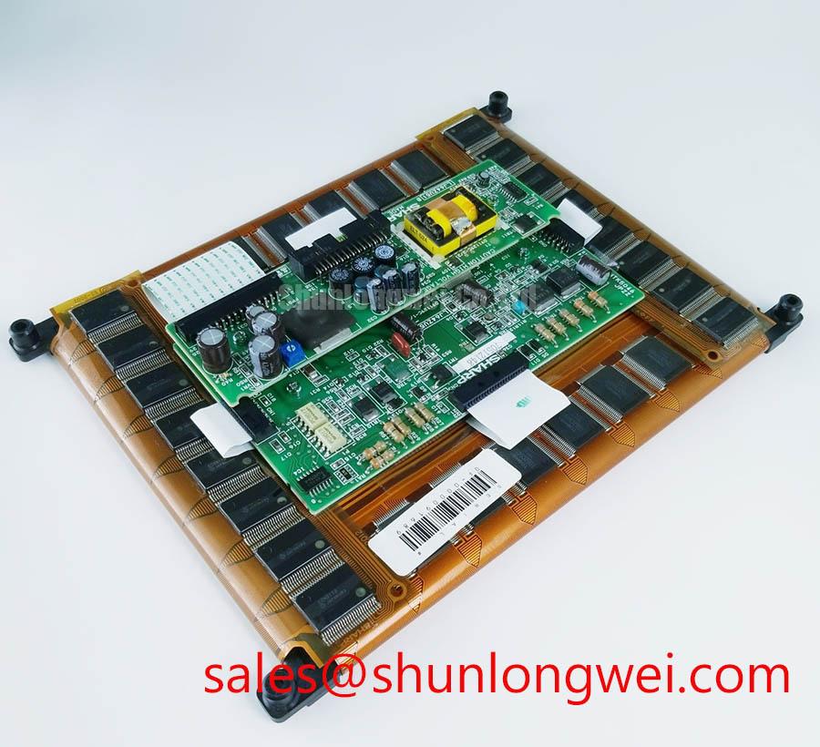
The backlight technology for this model is not confirmed in the supplied specification set. Do not assume that the LJ64ZU52 uses either a CCFL inverter or a constant current LED driver. The system integrator should verify the required backlight architecture from the original panel documentation and the installed machine wiring. If a legacy high voltage inverter is present, inspection should include the secondary transformer area, cable insulation, connector seating, chassis clearances, and evidence of arcing or carbon tracking, with all power removed before access.
High voltage testing is a system safety procedure rather than a factory rating for this display module. Any withstand or insulation test must follow the equipment manufacturer’s service documentation, the approved test method, and the limits applicable to the complete assembly. Polyimide is widely used in electrical insulation applications, but a general material reference such as the Polyimide Film High Voltage Dielectric Insulation reference does not establish the LJ64ZU52 insulation rating.
For systems using a separate LED driver, verify the current regulation, enable polarity, dimming method, startup behavior, and electrical noise at the panel connector. A display module should not be credited with EMC compliance for the completed machine. The controller, cable routing, shielding, enclosure, and driver layout determine the final result. The Sharp Display Solutions Official Portal can be consulted for manufacturer display information, while the exact replacement interface must still be matched against the original equipment documentation.
Surface Anti Glare and Anti Reflective Treatment for Ambient Readability
The supplied factory parameters do not confirm an anti glare coating, anti reflective treatment, viewing angle, contrast ratio, response time, or panel cell technology for the LJ64ZU52. Avoid assigning TN, IPS, or MVA characteristics from the product category alone. During a replacement evaluation, compare the visible surface under the actual machine lighting conditions, including reflections from cabin windows, protective covers, indicators, and overhead work lights.
For a telematics display considered for a heavy mining shovel or earthmoving equipment cab, mechanical compatibility should be checked together with optical performance. Confirm bezel contact, window alignment, connector access, cable bend clearance, vibration support, and sealing provisions. If a protective overlay is used, assess whether it introduces glare, reduces contrast, or presses against the active display area. Cold temperature behavior should be verified through the equipment qualification procedure because liquid crystal response, backlight output, and controller timing can vary with temperature. No specific sub zero response specification is provided for this model.
Selection work may also include a neutral comparison with the LM057QC1T08, but a similar application category does not establish interchangeability. Size, mounting geometry, active area, optical stack, connector position, timing, and electrical interface must be checked individually before any substitution is approved.
VESA Versus JEIDA Data Mapping and Even Odd Channel Signal Integrity
Before connecting the LJ64ZU52, identify the panel connector pinout from the original Sharp documentation and compare every signal name with the host controller. The supplied factory data does not specify LVDS or TTL operation, JEIDA or VESA mapping, logic supply voltage, power sequencing, differential impedance, channel arrangement, or pixel clock requirements. The system integrator should verify these details rather than treating common LCD interface practices as model specifications.
For a differential interface, inspect pair polarity, channel order, termination, shielding, reference return, and cable routing. If the controller offers a selectable JEIDA or VESA format, confirm the setting against the original panel data. Incorrect mapping may appear as abnormal colors, split images, unstable synchronization, or an apparently inactive screen. Such symptoms can also result from power sequencing, connector contact resistance, clock quality, or an incompatible timing table, so measurement against a known good signal path is appropriate.
Keep the display cable separated from noisy switching nodes and verify the complete assembly with an oscilloscope when image instability remains after the pinout has been checked. 💡 Pro Tip: Treat differential pair matching and return path continuity as layout requirements to be validated by the system engineer, not as guaranteed characteristics of the LJ64ZU52. For a complementary display system reference, the LQ10D321 may be reviewed as a separate component, but its presence does not confirm compatibility with this Sharp module.
Additional repair and evaluation context is available in The Ultimate Guide to Industrial TFT LCD Technology. Final approval should be based on verified electrical documentation, mechanical inspection, optical comparison, and functional testing in the target controller.