



Content last revised on October 16, 2026
Combating Contact Resistance Escalation across Gold Plated Bezel Fingers under Mechanical Vibration
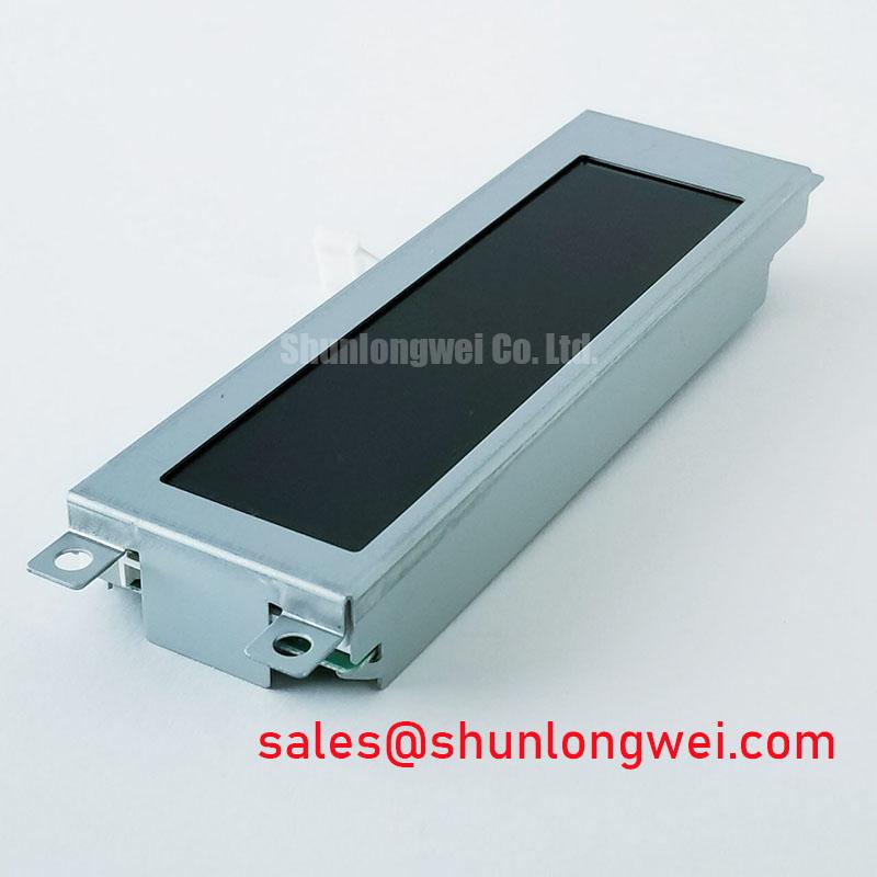
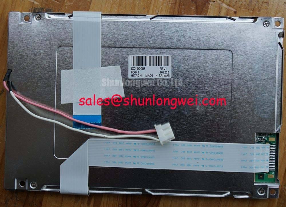
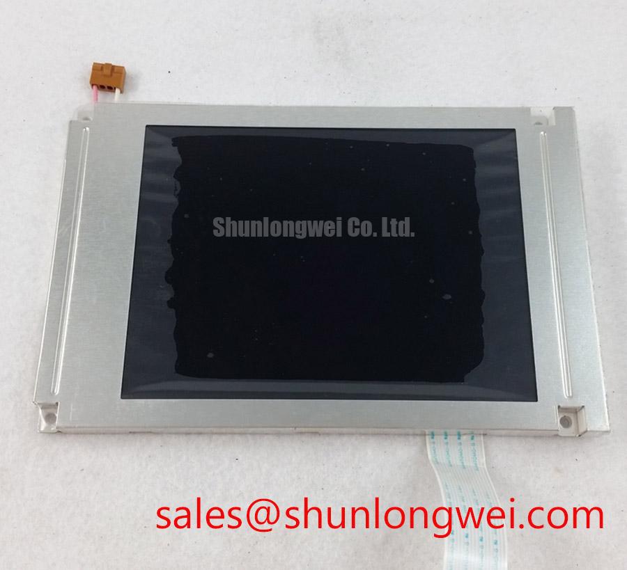
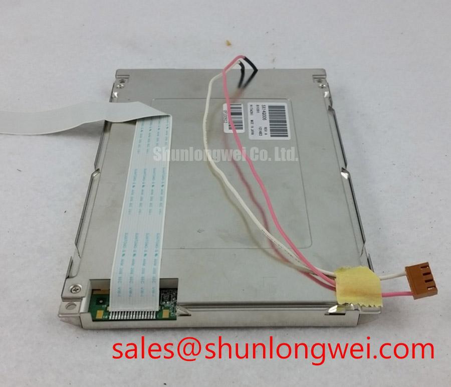
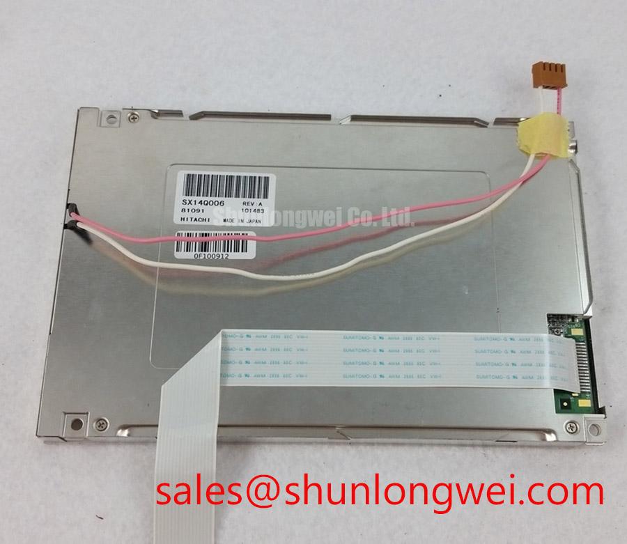
When a precision test instrument develops missing text rows, unstable contrast, or intermittent display updates, isolate the panel interface before replacing the display assembly. Check the connector seating, mounting pressure, control signals, and the bias supply while the unit is in its normal enclosure. The SX14Q006 is identified as a KOE / Hitachi LCD panel using an FSTN / STN monochrome passive matrix LCD panel construction. Compatibility work should begin with the original instrument drawing, connector arrangement, controller timing, and mechanical aperture.
For replacement work, the panel should be evaluated as part of the complete display chain. The host controller, frame memory, bias generation, contrast network, connector stack, and enclosure mechanics all influence the result seen by the operator. A panel with the correct nominal format can still produce poor readability if the control timing, bias reference, or connector compression differs from the original assembly.
Where the assembly uses an elastomeric zebra strip and bezel contacts, intermittent rows and columns often require attention at that interface. On a test and measurement instrument exposed to repeated handling or cabinet vibration, examine whether the connector remains laterally aligned across the full contact width. A small displacement can leave some conductive paths compressed while others make only marginal contact.
As a Design Consideration, a bezel assembly using an elastomeric connector may be evaluated around a compression pressure of 0.2 to 0.3 MPa, provided that the connector manufacturer and original mechanical design support that range. This is not an SX14Q006 factory specification. The practical objective is uniform pressure distribution without creating a local load point that distorts the panel edge or produces uneven optical pressure.
Remove the panel only after the instrument is isolated from its supply and any stored energy has been discharged. Inspect the contact fingers under magnification for surface contamination, oxidation, displaced adhesive, or marks that reveal uneven clamping. Where the assembly permits cleaning, use anhydrous IPA on a lint free swab and allow the contact area to dry fully before reassembly. Avoid abrasive treatment that can change the contact geometry or remove the surface finish.
During reassembly, tighten the bezel progressively across opposing locations so the load is distributed evenly. A display that changes when the frame is pressed should prompt controlled inspection of the mechanical interface, rather than being taken as proof of a failed LCD cell. Check the connector position again after the instrument has reached its normal operating temperature, because enclosure expansion can alter the effective pressure.
Latch Pulse and Frame Synchronization Pulse Alignment to Eliminate Line Smearing
Line smearing on a monochrome passive matrix panel should be investigated through the relationship between frame synchronization, line latch, and dot clock signals. In a typical parallel interface, FLM establishes frame position, LP transfers a line into the column drive path, and CP advances pixel data. The correct signal names and polarity must come from the panel and original controller documentation and wiring record.
Use a known-good display path or the instrument service waveform as the reference. Observe whether LP edges remain consistently positioned relative to CP and whether FLM arrives at the expected frame boundary. Excessive cable length, poor return paths, ground bounce, or an unsuitable logic threshold can reduce timing margin. The system engineer should verify the complete timing relationship with an oscilloscope at the panel connector rather than judging alignment from the appearance of the characters alone.
Power sequencing also deserves attention. A Design Consideration for passive matrix LCD integration is to establish the logic supply before applying the LCD bias supply, where required by the panel documentation, then confirm that shutdown does not leave an uncontrolled DC bias across the liquid crystal. The exact order, delay, voltage limits, and timing of drive signals must follow the controller and panel documentation.
For contrast instability, monitor the bias supply and contrast reference identified by the host design. Labels such as VEE and V0 may identify different circuit nodes, so confirm their functions and voltage references from the schematic. The range of −15 V to −24 V and ripple target below 20 mVpp may be used only as a design review reference when supported by the original circuit. They are not confirmed SX14Q006 factory ratings. Ripple should be correlated with visible contrast movement, frame activity, and temperature rather than treated as a single-cause diagnosis.
At the signal path level, the SX14Q006 should not be treated as a modern LVDS display without evidence from the original equipment. If a conversion board is being considered, verify the interface type and logic levels from the panel and host documentation, and evaluate clock integrity at the panel connector. The commonly used 100 ohm differential pair rule applies to differential links and does not automatically define a passive matrix panel interface.
Direct Sunlight High Ambient Readability without Active Backlight Illumination
When the instrument is readable mainly through ambient illumination, inspect the optical stack for gradual contrast loss, haze, bubbling, and localized discoloration. A transflective or reflective installation can lose practical readability when the polarizer, adhesive layers, or front window have aged, even though the digital data remains correct.
The SX14Q006 classification identifies an FSTN / STN monochrome passive matrix LCD panel; it does not by itself confirm reflective or transflective operation, or the use of a particular polarizer formulation, adhesive system, or optical treatment. For a legacy precision instrument, compare the panel under the same viewing angle and ambient light used in service. A change in contrast between direct sunlight and controlled bench lighting can help separate optical aging from a controller or bias problem.
UV exposure, thermal cycling, and enclosure contamination should be considered when inspecting a panel used near windows or under strong industrial lighting. Look for adhesive bubbles that expand with temperature, edge lifting, and areas where the front surface no longer sits uniformly against its frame. These observations support an optical and mechanical review; they do not establish a specific internal failure mechanism without component analysis.
The timing interface remains relevant even when the problem appears optical. Check CP, LP, and FLM for edge movement or jitter during the same brightness condition. If the host offers four bit or eight bit data modes, confirm the mode from the original controller configuration and panel documentation instead of assuming compatibility. A stable image with reduced contrast points toward a different investigation path than characters that smear only during bus activity.
For background on liquid crystal behavior, engineers may consult Liquid Crystals.
On Board Charge Pump versus External DC DC Negative Bias Supply Ripple Suppression
Contrast fade at temperature extremes should be assessed at the bias generation stage, especially where the original instrument uses either an onboard charge pump or an external negative supply. Record the bias voltage at the panel connector while the display is idle, updating, and operating after thermal stabilization. Compare the rail behavior with the displayed contrast and with the controller load state.
Use the original circuit topology to determine whether the panel receives a regulated negative rail or a temperature compensated bias reference. A thermistor network can change contrast over temperature, but its resistance curve, placement, and control relationship are system characteristics rather than confirmed SX14Q006 specifications. The replacement assessment should preserve the original control philosophy unless the instrument designer has validated a new calibration method.
Ripple suppression is best evaluated at the point where the panel is connected. Probe grounding, switching current return paths, and cable routing can introduce measurement artifacts or couple servo noise into the bias rail. Minimize the high current switching loop and keep sensitive display references away from noisy motor or converter paths, then verify the remaining ripple under the operating conditions that produce the visible defect.
Where the panel edge uses a zebra connector, the electrical and mechanical checks remain linked. An apparently unstable bias symptom can be aggravated by a connector that changes contact pressure as the enclosure warms. Reinspect alignment after thermal cycling and clean permitted contact surfaces with anhydrous IPA before repeating the contrast test.
For a replacement review involving the LM32K071, engineers must compare its specifications against the original mechanical opening, connector position, timing arrangement, and optical requirements. No interchangeability with the SX14Q006 is established here. The following comparison leaves unconfirmed interchange parameters for documentation review.
| Evaluation item | SX14Q006 | LM32K071 |
|---|---|---|
| Manufacturer or family reference | KOE / Hitachi | Consult product documentation |
| Panel classification | LCD panel | Consult product documentation |
| Display technology | FSTN / STN monochrome passive matrix LCD | Consult product documentation |
| Mechanical fit | Verify against the original installation | Verify against the original installation |
| Interface and optical interchangeability | Verify from the original instrument records and panel documentation | Verify from the product documentation |
For related display chain planning, the LM12S49 reference may help engineers review how a passive display interacts with its controller and bias circuitry. The SX14Q006 should be released for service only after the replacement panel, connector compression where applicable, timing signals, contrast rail, and enclosure fit have been checked together.
Maintenance Note: Inspect the cabinet cooling path and display sealing pad during scheduled service, because dust buildup or a degraded gasket can increase thermal stress and allow mechanical movement around the panel.
For broader maintenance planning in industrial operator interfaces, use the Industrial Display and HMI Solutions reference alongside the instrument service documentation.