



Content last revised on September 12, 2026
AA050AA11 Inspection and Integration Overview
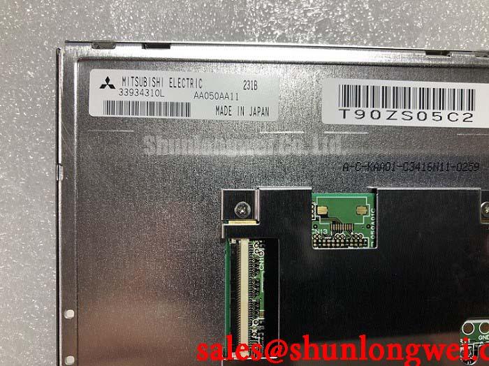
Before connecting the AA050AA11, inspect the TFT-LCD display module, mating connector area, cable retention features, and enclosure contact surfaces for handling damage, contamination, or mechanical distortion that could affect installation.
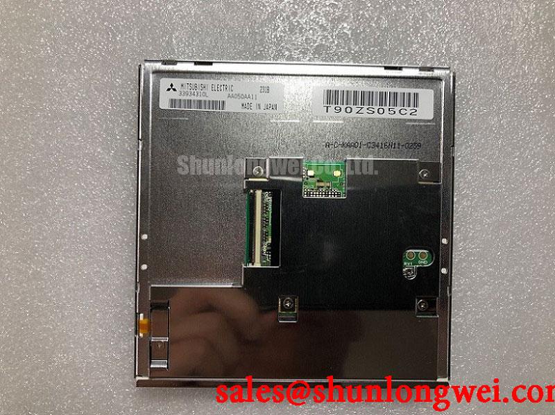
The AA050AA11 is an Industrial Grade LCD/HMI Panel manufactured by Mitsubishi Electric and supplied as a TFT-LCD Display Module. The available official product data identifies the product category, manufacturer, and module type; electrical interface details, optical values, pin assignments, mechanical drawings, touch construction, backlight requirements, and environmental limits should be verified from the original panel documentation before replacement or new-system integration.
For repair engineers, the practical starting point is to compare the installed display’s label, physical mounting arrangement, connector orientation, cable part number, and host controller configuration with the intended AA050AA11 assembly. A panel can fit within an enclosure while still being incompatible at the signal-mapping, power-sequencing, or backlight-control level.
Surface Readability Review for Anti Glare and Anti Reflective Requirements
High ambient illumination can make an industrial HMI difficult to read even when the image source is functioning correctly. Surface anti-glare and anti-reflective treatments are often evaluated for vehicle terminals, warehouse equipment, and outdoor-adjacent operator stations because reflected light can mask dark characters, status icons, and alarm colors. The official structured information available for the AA050AA11 does not confirm an anti-glare coating, anti-reflective coating, contrast ratio, luminance rating, or viewing-angle specification. These characteristics should therefore not be assumed for this model.
During an incoming inspection, assess the visible face of the module under controlled ambient lighting and compare it with the original installed panel. Look for reflection patterns, image washout, uneven dark areas, discoloration, and haze that could be caused by the front protective window, a bonding layer, a host enclosure lens, or the display itself. This comparison is especially relevant when the module is being evaluated for an AGV or forklift telematics display, where the final readability depends on the panel, protective cover, viewing angle, and illumination entering the cab or equipment enclosure.
Panel technology also matters when reviewing grayscale behavior from off-axis positions. TN, IPS, and MVA are distinct display architectures with different viewing characteristics, but the supplied official information does not identify the underlying panel mode of the AA050AA11. It would be inaccurate to assign a symmetric viewing cone or claim mitigation of grayscale inversion without the original Mitsubishi Electric documentation. System integrators should assess the actual viewing direction, expected operator posture, mounting tilt, and image behavior using the intended host electronics.
Optical contrast under sunlight or bright factory lighting is a system-level result rather than a property that can be inferred from a product category alone. The enclosure window, cover-lens reflectivity, display brightness setting, backlight condition, and contamination on external surfaces can each change perceived contrast. When replacing a failed screen, preserve the original bezel stack and inspect whether an additional optical film or protective lens was present in the original equipment.
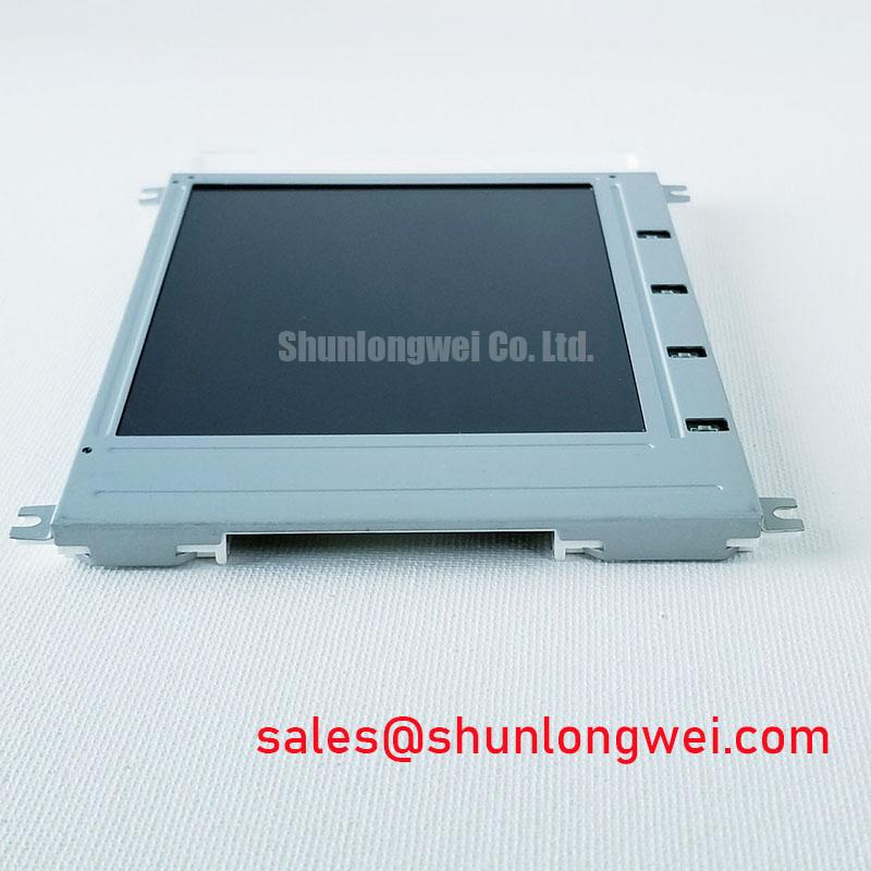
Where a different module is under technical evaluation, LM64P10 can be reviewed as a separate display-module reference. Physical similarity alone should not be treated as proof of interchangeability. Engineers should compare the manufacturer documentation for dimensions, mounting points, electrical interface, display timing, and optical requirements before making an integration decision.
Controlled Differential Signal Routing and Display Data Mapping Checks
Before applying power, verify the original panel documentation for the required logic supply, connector pinout, signal protocol, power-on sequence, and backlight-control arrangement. The available official product information for the AA050AA11 does not state whether its host interface is LVDS, TTL, or another signaling arrangement. It also does not state the required logic supply voltage. These values must be confirmed from the original panel documentation and the equipment schematic rather than inferred from connector appearance or from another Mitsubishi Electric display family.
LVDS installations require attention to differential-pair continuity, pair polarity, reference grounding, connector seating, and the display controller’s data format. JEIDA and VESA mappings are not interchangeable merely because the same connector style is present. A mapping mismatch can present as abnormal colors, divided image regions, missing pixel information, or unstable graphics. Such symptoms may also arise from a damaged cable, insufficient power integrity, an incorrect timing-controller configuration, or a fault on the host board, so measurement against a known-good signal path remains important.
Controlled differential impedance is a Design Consideration for interfaces that use differential signaling. The required routing geometry depends on the display interface specification, cable construction, PCB stackup, connector transition, controller output characteristics, and electromagnetic environment. Designers should keep paired routes consistent, avoid unnecessary discontinuities, and validate waveform quality at the installed module rather than imposing a generic routing target on an undocumented interface.
Power sequencing deserves the same discipline. A display may remain blank, show intermittent image content, or experience unstable startup when the panel supply, logic signals, enable controls, and backlight subsystem are not handled in the order required by its documentation. Check the host controller timing, supply ramp behavior, connector contact condition, and grounding arrangement with suitable instrumentation. Do not attach or remove the display cable while power is present.
💡 Pro Tip: Keep differential signal pairs routed as matched pairs through the host board and cable path, then verify pixel-clock and data integrity, where applicable, on the completed equipment rather than relying on visual cable inspection alone.
In high-noise industrial equipment, radiated and conducted interference can affect the controller, cable assembly, power converter, or display interface. No claim is made here that the AA050AA11 independently meets system EMC requirements, because EMC compliance applies to the completed equipment configuration. Shield termination, enclosure bonding, cable routing, controller layout, and switching loads should be evaluated at the system level.
Industrial Bezel Fit and Mounting Load Control
The mechanical fit of a replacement display should be confirmed before any permanent fastening is applied. Compare the host enclosure opening, active viewing area, front bezel overlap, rear clearance, connector exit direction, cable bend space, mounting-hole location, and any support pads with the original equipment documentation. The supplied official information confirms that the AA050AA11 is a TFT-LCD display module, but it does not provide verified dimensions, mounting-hole details, screw sizes, bezel tolerances, or fastening torque values. Those values should be obtained from the original module drawing or equipment service documentation.
Mounting loads are a Design Consideration, particularly where a display is clamped behind a rigid front panel. Uneven clamping can create local stress that becomes visible as brightness nonuniformity, pressure marks, color shift, or dark-field mura. These observations do not prove a single root cause. They should prompt an inspection of the mounting sequence, enclosure flatness, support points, gasket compression, and whether the display was forced into an opening that does not match the original mechanical envelope.
When the host design uses multiple fasteners, tighten them progressively in a balanced cross pattern while following the equipment manufacturer’s documented torque requirement. Avoid treating generic screw-torque practices as an official AA050AA11 specification. The correct mechanical limit depends on the screw type, thread engagement, bracket material, spacer arrangement, panel construction, and original assembly design.
AGV and forklift telematics installations can introduce vibration and repeated mechanical loading through the equipment chassis. This does not establish a vibration rating for the display module. It does mean that cable strain relief, bracket stiffness, connector retention, and enclosure alignment should be checked as part of compatibility assessment. The display should not be expected to correct a loose mounting frame, a misaligned protective window, or a cable path that transfers equipment movement directly into the connector.
Touch operation also requires separate verification. The official product information provided does not identify an integrated touch technology for the AA050AA11. Capacitive and resistive touch overlays have different controller, cover-lens, glove-use, moisture-response, grounding, and mechanical-stack requirements. A system integrator should verify whether touch functionality is part of the original panel assembly or is implemented as a separate equipment-level component.
Mechanical Stress Screening and Image Fault Isolation
Use a repeatable bench check to separate visible image faults from host-system faults. With the display connected according to the verified equipment documentation, inspect full-field primary colors, neutral gray, black, and white images. Observe the screen from the normal operating position and from moderate off-axis positions. Record whether the issue follows the image content, remains fixed in one location, changes after cable movement, or appears only after the equipment has reached operating temperature.
Fixed vertical or horizontal lines, localized color changes, intermittent regions, and full-screen image loss can have several possible sources. These include the module, its flex interconnects, the host cable, connector contact condition, timing configuration, supply behavior, or the graphics controller. Avoid assigning a fault to internal glass or driver structures solely from one visual symptom. Compare with the original module when available and inspect the signal path with appropriate test equipment.
An oblique flashlight inspection can help distinguish a missing image from a display that is producing image content without expected illumination. With care to avoid contact pressure on the front surface, use reflected light to determine whether faint graphics remain visible. A faint image may indicate that the display data path is active while the backlight path, enable control, supply, connector, or associated host circuitry requires further investigation. It is not by itself a confirmed diagnosis of the module.
Do not press on the active display area to test an intermittent defect. Pressure can alter the symptom temporarily while adding mechanical stress, making later diagnosis less reliable. Instead, inspect the bezel fit, mounting supports, cable retention, connector latch engagement, and controller-board connection under unpowered conditions before repeating the powered test.
For broader fault-isolation methods involving cabling, power sequencing, display-controller behavior, protective windows, and industrial HMI integration, see Industrial Display & HMI Solutions. Use the original AA050AA11 documentation as the governing source for model-specific electrical, mechanical, optical, and environmental acceptance criteria.