Content last revised on October 17, 2026
Industrial EMI Noise Immunity, Chassis Shielding Continuity and Common Mode Ferrite Chokes
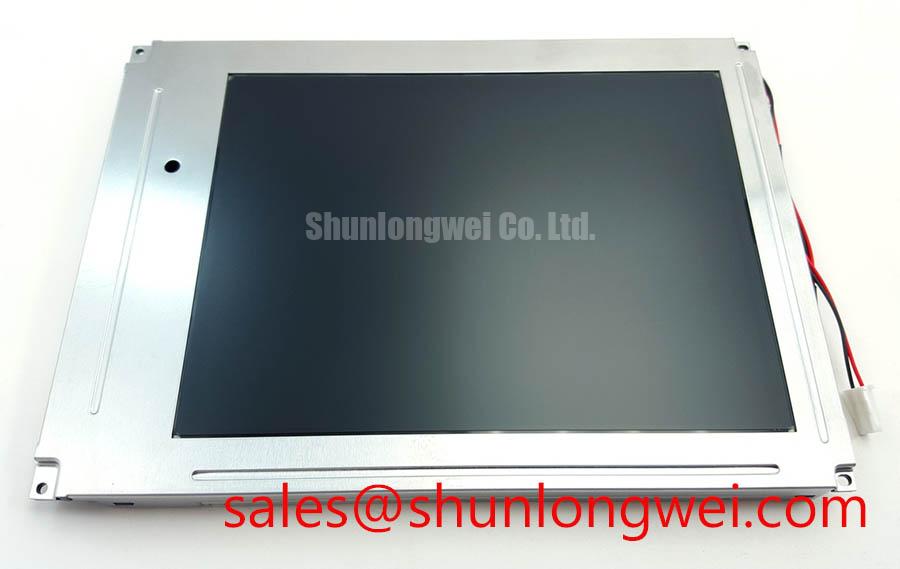
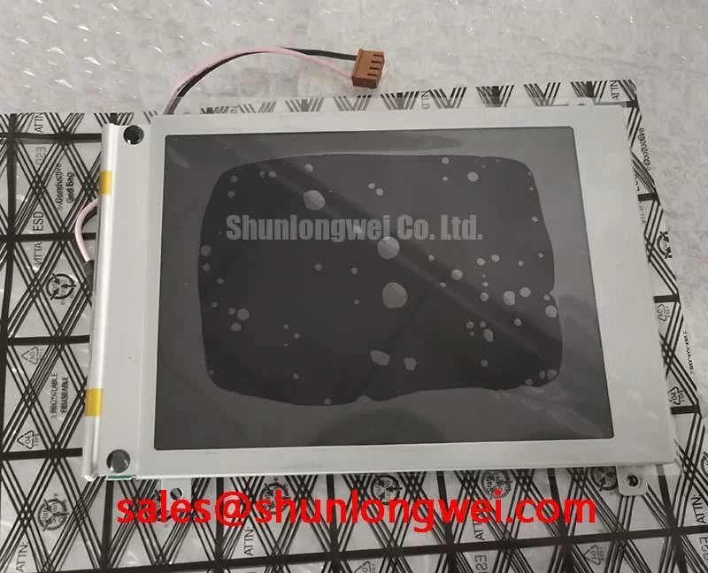
Manufacturer: Tianma, Class: Industrial Grade LCD/HMI Panel, Package: TFT-LCD Active Matrix Color Display Module, Status: Decoded Baseline / Standard Form Factor
When horizontal noise bands or unstable pixels appear near a variable frequency motor drive, begin at the display cable and chassis bond rather than replacing the panel immediately. Inspect the full FFC or LVDS route for pinched sections, uneven connector insertion, and shield discontinuities at the enclosure entry. The TM070RDHG24 is identified as a TFT-LCD active matrix color display module; the surrounding cable, grounding path, and host timing circuit determine how effectively the display interface tolerates industrial electrical noise.
A 360 degree shield termination can reduce the area available for common mode current to circulate, provided the shield is bonded to the intended chassis reference at the equipment level. This is a Design Consideration, not an official feature claim for the panel. Common mode ferrite components may also be evaluated where conducted noise is coupled into the display cable, but their impedance curve, saturation behavior, and placement must match the actual cable and switching environment.
For differential display links, keep the pair geometry consistent through the connector transition and avoid unnecessary stubs. The system designer should establish the target differential impedance and allowable skew from the host interface documentation, then verify the result with the actual cable, connector, and enclosure installed. A scope comparison between a known good signal path and the suspect path can reveal ringing, common mode movement, or timing distortion that a simple continuity check will miss.
Power and signal references deserve the same attention. Check whether the panel ground returns through a long mechanical path while the signal shield is bonded elsewhere, since that arrangement can produce visible interference even when every conductor passes a static continuity test. The TX17D02VM2CAA-2 may serve as a reference point when comparing another display form factor or resolution class, but mechanical fit, interface definition, and optical behavior still require an equipment specific review.
💡 Bench Tip: Disconnect power before inserting or removing the display cable, then lock the FFC completely flush so the contacts are not left partially engaged.
Flashlight Dark Shadow Optical Diagnostic to Isolate Logic and Backlight Failure Modes
Use a controlled full screen test with primary colors, white, black, and neutral gray to separate image generation problems from illumination problems. A dark screen with a flashlight held at an oblique angle can show whether image content remains present beneath a weak or absent backlight. If characters or color blocks become visible only under the flashlight, continue the investigation around the backlight power path, connector seating, and brightness control signal.
When the image itself contains a fixed line, localized region, or intermittent column, observe whether the defect follows the displayed content or stays fixed at the same physical position. A content dependent defect directs attention toward the host signal and timing path. A fixed defect calls for careful inspection of the panel edge, flex connection, and mechanical pressure around the display opening. These observations help prioritize the next measurement without assigning a single cause to one symptom.
Run the optical check at several brightness settings and allow the panel to reach a stable operating condition before judging uniformity. Record visible dark corners, bands, color temperature changes, and areas that respond differently during brightness transitions. A replacement assessment should compare the complete display assembly under the same enclosure, diffuser position, ambient light, and camera exposure, because a camera can exaggerate nonuniformity that is less visible to the operator.
Backlight aging must be treated as a system question. The available product information identifies the part as an industrial LCD/HMI panel but does not establish a model specific luminous maintenance curve or field life result. Designers should therefore evaluate the actual driver current, thermal path, brightness target, and duty cycle when planning long term operation. Tianma’s industrial display information at Tianma NLT Industrial TFT-LCD Display Technologies provides useful manufacturer context for industrial display evaluation.
Backlight Constant Current Driving, PWM Dimming and Flicker Suppression
Confirm the installed backlight architecture from the original panel documentation before connecting a replacement driver. The TM070RDHG24 product record supplied for this page does not specify a backlight voltage, current, dimming ratio, or control frequency, so the host circuit must be matched to the documented panel interface rather than treated as interchangeable with another display.
For an LED backlight system, a constant current driver normally regulates light output more consistently than a voltage source whose current changes with temperature and device variation. That principle belongs to the system design and does not establish a confirmed electrical rating for this model. During bench evaluation, monitor the driver output while changing brightness and look for overshoot, audible switching artifacts, unstable startup, or visible modulation in a camera view. The selected PWM frequency and duty cycle should be determined from the driver, host controller, visual performance requirement, and acoustic environment.
Power sequencing also affects the first image. Verify that the display supply, logic interface, reset behavior, and backlight enable signal follow the timing required by the original panel documentation. White screens, delayed images, or residual glow during shutdown can arise from an unsuitable sequence, an undefined control state, or stored charge in the system wiring. Capture startup and shutdown behavior with the panel connected to its intended controller, then compare it with the known good assembly.
Where the display is integrated into an HMI console, CNC operator pendant, variable frequency drive cabinet, or railway passenger information terminal, the enclosure designer should evaluate airflow, cable strain relief, service access, and electromagnetic coupling together. The related TX18D35VM0APB-2 can be reviewed as a separate display solution in the same broader system discussion, while its electrical compatibility remains a separate engineering decision.
Grayscale Performance, Viewing Direction and Alignment Considerations
Check grayscale visibility from the real operator position before approving a panel replacement. A display that appears acceptable when viewed directly can show tonal reversal, reduced contrast, or color shifts when the operator looks from above, below, or across the console. These effects depend on the panel technology, viewing direction, image content, ambient light, and cover window geometry. The supplied TM070RDHG24 data identifies the product category and construction, but it does not provide a confirmed viewing angle, surface treatment, contrast value, or panel technology designation for publication here.
Use gray ramps, fine text, warning symbols, and low contrast interface elements during the evaluation. Compare the screen from the expected eye positions while adjusting the enclosure angle only within the intended mechanical range. A glossy cover, protective window, or strong overhead light can create reflections that resemble poor grayscale performance. The optical stack and enclosure should therefore be assessed as an assembly, with the display surface kept clean and the test illumination recorded.
Static industrial HMI screens also require a content management review. Rotate fixed status elements where the application permits, use appropriate brightness for the ambient environment, and observe whether any residual image remains after the screen changes. This is a Design Consideration for the complete display system rather than a model specific burn in guarantee. Long term evaluation should include the actual UI layout, backlight setting, thermal conditions, and operating schedule.
Mechanical integration has a direct optical effect. The FPC should leave its natural bend path free from sharp folds, and the connector should be supported so cable movement does not transfer force into the panel edge. If optical bonding, sealing, or a protective cover is added, the integrator should verify moisture resistance, trapped air, pressure distribution, and readability under the intended ambient light. The technical principles behind these checks are discussed in The Ultimate Guide to Industrial TFT LCD Technology. Additional industrial TFT display references are available from Tianma Microelectronics Industrial TFT Displays.