Content last revised on October 17, 2026
Chassis M3 Fastener Torque Assessment and Optical Mura Inspection
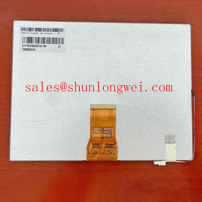
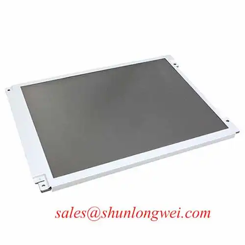
With the display assembly disconnected, inspect the bezel contact surfaces, cable exit, and mounting points before comparing any visible pressure marks with the powered image. The TM080SDH02-41 from Tianma is a TFT-LCD active matrix color display module identified for industrial LCD/HMI integration. Mechanical fit, controller compatibility, and optical performance should be assessed together when evaluating a replacement.
The supplied product baseline establishes the manufacturer, model, and module category. For replacement approval, record the original panel’s outline dimensions, active area, connector assignment, supply requirements, timing, backlight specifications, and environmental ratings in the comparison sheet and verify them against the applicable datasheet. Retain the complete TM080SDH02-41 designation throughout purchasing and engineering review so that a similar family name does not become an unintended substitution.
Inspect whether the enclosure transfers fastening load through its intended mounting features or directly onto the display perimeter. As a Design Consideration, compare the bezel opening, panel seating surface, and cable clearance with the assembly drawing. Uneven supports, trapped cables, and displaced cushioning can introduce localized stress; an image change during controlled assembly assessment can help locate the affected region without establishing a single root cause.
Where the host chassis uses M3 fasteners, select tightening conditions from the enclosure specification, thread engagement, and mounting hardware. A screw designation alone does not establish an acceptable torque for this display. During an approved assembly procedure, progressive tightening across opposing mounting points can help distribute enclosure load. Inspect uniform gray and dark images at successive assembly stages, keeping brightness and viewing position consistent.
Cold image lag requires a separate assessment from pressure related mura. As a Design Consideration, lower liquid crystal temperature can slow optical transitions, while mechanical stress can produce spatial nonuniformity. Compare transition behavior after temperature stabilization and inspect whether persistent patches follow enclosure contact locations. Any enclosure heating arrangement should be evaluated through the equipment’s thermal controls and panel limits.
For replacement sourcing, include TX26D211VM0BAB only as a separate comparison candidate. Approval requires matching its documented mechanical, electrical, optical, and timing characteristics against the original assembly; the link does not establish interchangeable fit.
Polarizer Durability and Optical Film Inspection under Direct Industrial Lighting
Examine the display surface under both diffuse room light and the installation’s directional lighting, using the same test image and viewing position. As a Design Consideration, reflections, surface contamination, viewing angle behavior, and uneven illumination can each affect perceived readability. Inspect the cover window separately where accessible, because its reflections or haze can obscure the panel’s own optical behavior.
TN, IPS, and MVA describe different liquid crystal operating approaches with different angular characteristics. These general distinctions do not identify the operating mode of the TM080SDH02-41. Evaluate grayscale visibility from the intended operator positions rather than transferring another panel’s viewing angle specification. Likewise, establish any anti-glare or anti-reflection treatment from the panel and cover window specifications before selecting cleaning materials or judging surface wear.
For a marine radar or navigation bridge console, compatibility evaluation should include readability through the installed window, enclosure protection against salt contamination, and usable brightness adjustment. These are equipment integration requirements, rather than evidence of a marine qualification for the panel. Manufacturer resources at Tianma NLT Industrial TFT-LCD Display Technologies provide broader industrial display technology context.
As an Engineering Recommendation, assess the existing backlight controller across its supported dimming range while monitoring light output, drive behavior, and acoustic response. PWM frequency alone does not establish flicker performance: pulse shape, low brightness behavior, and controller operation also matter. Select operating conditions through the actual driver specification and system measurements.
Display Connector Verification, Pixel Clock, and LVDS Mapping
Identify the connector contacts and signal assignments before connecting a replacement cable. Connector appearance and contact count do not establish the electrical interface. Trace the host schematic to distinguish supply, return, control, and image signals, then compare those assignments with the panel connection drawing. Include connector orientation and cable contact side in the review.
Where the documented interface is LVDS, verify transmitter configuration, channel arrangement, data width, and receiver mapping together. JEIDA and VESA mapping differences concern how pixel information is assigned to transmitted data positions; differential clock quality alone cannot resolve a mapping mismatch. If abnormal colors or image boundaries appear, compare controller configuration and timing with a known working configuration before attributing the symptom to the panel.
Pro Tip: Where LVDS is confirmed, preserve differential pair continuity and control relative routing length according to the transmitter and receiver timing budgets, then validate signal quality through the installed cable.
As a Design Consideration, examine supply startup, reset behavior, image data validity, and backlight enable against the specified sequence. Measure at the panel connection where practical, since cable resistance and connector behavior can change conditions from those measured at the controller. Probe loading and access arrangements should also be considered when interpreting clock or data waveforms.
The TX18D216VM0BAA is another display product that can be documented separately during a system sourcing review. It should not be treated as a backlight driver or a confirmed companion to this module. Broader manufacturer information is available through Tianma Microelectronics Industrial TFT Displays.
Thermal Cycling Assessment of Optical Layers and Enclosure Seals
Compare image uniformity, transition behavior, and enclosure condition before and after temperature exposure within the documented assembly limits. As a Design Consideration, differential expansion can change mounting pressure, while temperature can alter optical response. Record whether an observed change disappears after stabilization or persists under the original inspection conditions.
Inspect accessible perimeter surfaces for displacement, lifting, trapped moisture, or changed contact with the enclosure seal. Keep observations specific to the visible assembly rather than assigning an undocumented adhesive or sealant chemistry. The Industrial Display & HMI Solutions engineering guide offers wider context for enclosure and environmental assessment.
When investigating brightness loss, separate the panel’s optical behavior from the external backlight supply and controller. As an Engineering Recommendation, check supported current regulation, dimming response, temperature behavior, and any documented protection status. Open circuit, short circuit, and overvoltage responses belong to the relevant driver specification. Interpret fault outputs through that controller’s documentation and approved test procedure, then compare restored operation at the same brightness setting and stabilized temperature.