Content last revised on October 14, 2026
Display Interface Timing, Pixel Clock & Signal Integrity
I check the connector drawing against the host cable before evaluating an image fault on the TM080XDH02. Connector count alone does not establish interface compatibility: the signal assignments, contact orientation, supply connections and controller timing must match. Establish the actual interface from the matching panel documentation before attaching a test controller.
Design Consideration: For an LVDS integration, compare the controller’s pixel clock, active image dimensions, blanking intervals and data mapping with the panel requirements. JEIDA and VESA mapping differences can produce incorrect colors or grayscale even when synchronization appears stable. A divided image, displaced content or intermittent vertical boundary warrants comparison of the complete timing configuration rather than an immediate panel replacement.
Inspect the cable seating and strain relief before probing signals. A latch can appear closed while the flexible cable remains slightly skewed. Examine contact alignment without scraping the contacts, then compare the suspect cable with a known working assembly of the same specification. When measuring differential signals, use a suitable probe and avoid adding long measurement leads that change the signal path.
Capture the panel supply, interface activity and backlight enable during startup. Compare their order and transitions with the documented sequence, including shutdown behavior. Cable routing, differential impedance and pair skew belong to the host interconnect design; their acceptance limits should follow the interface requirements and measured signal quality rather than an assumed universal setting.
💡 Bench Tip: Remove power and use appropriate ESD protection before seating the display cable squarely and closing its retaining latch.
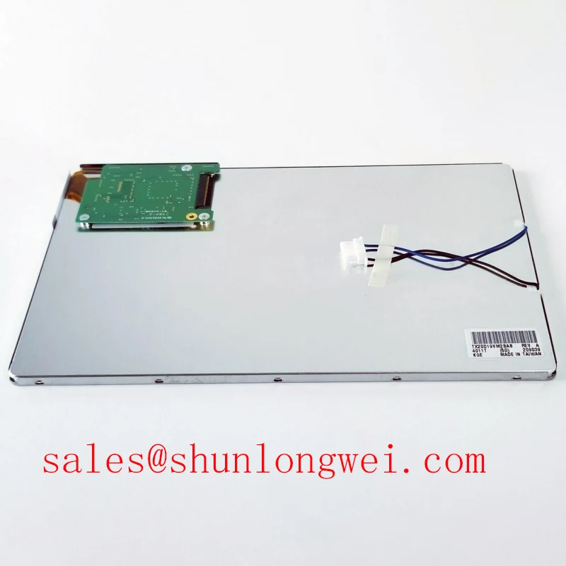
For replacement evaluation, compare the Tianma TM080XDH02 with the TX20D28VM2BPA only after checking resolution, outline, mounting, interface and backlight requirements; the latter is an evaluation candidate, not an established direct replacement. CNC operator panels and robot teach pendants are potential integration contexts, subject to those checks and the equipment’s environmental requirements.
Radiated Emissions Assessment (CISPR Class A/B) & Backplate Grounding
Compare the displayed test pattern with nearby switching equipment inactive and operating, while keeping the controller configuration and cable position unchanged. Horizontal noise bands or pixel instability that track equipment operation justify investigating conducted and radiated coupling, but do not identify a single cause. Record the operating condition alongside the observed image disturbance so subsequent cable and bonding changes remain comparable.
Design Consideration: Where the host assembly uses a shielded display cable, inspect the shield termination and enclosure bonding for continuity and mechanically secure contact. Shield termination geometry matters at high frequencies. A short, broad connection can behave differently from a long grounding lead, and the appropriate arrangement depends on the enclosure and cable construction. Ferrite suppression is a system-level option to evaluate through measurements, not a standard accessory of the TM080XDH02.
Do not treat “multi-point” and “star” grounding as interchangeable recipes. Their usefulness depends on the current return paths and frequency range involved. The assembled equipment must undergo the applicable emissions assessment; an LCD module does not independently establish CISPR Class A or Class B compliance. Repeat disturbance checks after enclosure bonding or cable routing changes rather than judging success solely from a clean image.
Keep optical readability separate from electrical noise diagnosis. Compare identical test images under controlled room lighting and the intended ambient illumination, noting reflections from the installed cover window. Contrast measured under one lighting condition does not establish sunlight readability. Anti-glare treatment must be identified from the actual assembly specification, not inferred from surface appearance. The Tianma Microelectronics Industrial TFT Displays website provides manufacturer context, while Industrial Display & HMI Solutions provides broader integration guidance.
Backlight Constant-Current Driving, PWM Dimming & Flicker Suppression
Display full-screen white, black, red, green and blue patterns before judging backlight performance. These patterns help separate persistent pixel defects from broad illumination variation and signal-related artifacts. Record the location and appearance of suspected defects at consistent brightness and viewing position, then apply the procurement agreement’s pixel acceptance criteria rather than inventing a pass limit.
LED driving and PWM dimming are driver evaluation subjects here, not established TM080XDH02 specifications. Identify the panel’s backlight connections and matching driver requirements before energizing the illumination circuit. A driver intended for a different backlight assembly is not interchangeable simply because its connector fits.
Design Consideration: For a documented LED backlight integration, evaluate current regulation across startup, steady operation and commanded dimming. Check the driver output waveform together with optical output, preferably using a photodetector. PWM duty cycle does not necessarily translate into proportional perceived brightness, particularly near the driver’s minimum controllable pulse width. The operating frequency and dimming range should be selected and validated within the actual driver and panel limits.
Listen for dimming-dependent noise while checking for visible flicker, but distinguish electrical modulation from camera exposure artifacts. Compare center and edge luminance using fixed measurement geometry, and assess color uniformity with an appropriate instrument. Record warm-up behavior before comparing readings. Brightness maintenance, LED lifetime and MTBF describe different properties; none supplies a service-life guarantee for this model without the corresponding manufacturer specification and test conditions.
Aluminum Heat Spreader Sizing & Thermal Interface Placement along Narrow Display Edges
Map temperatures around the mounted display edges after the enclosure reaches a stable operating condition, then compare the pattern with visible brightness variation. Measure with the intended backlight setting and enclosure configuration. A local temperature rise deserves investigation, but its position alone does not prove a defective backlight or establish the panel’s internal material construction.
Design Consideration: If the equipment uses aluminum heat-spreading rails, evaluate their contact area and heat path without transferring assembly pressure into unsupported display surfaces. Thermal interface placement must preserve cable clearance, mounting geometry and the panel’s permitted contact regions. Avoid using the display frame as a convenient compression stop unless its mechanical drawing explicitly supports that load.
Repeat white-field and grayscale checks after fastening the display into its intended housing. Changes in shading or edge appearance can justify examining bezel pressure, mounting alignment and cable strain. Compare the installed result with a minimally constrained bench setup, keeping image settings unchanged. Assess reflections through the final protective window separately from backlight uniformity.
For cold-start evaluation, soak the assembly within its documented operating range and observe startup, grayscale transitions and recovery as it warms. Slower liquid-crystal response can affect moving content without indicating a timing fault. Any host-side compensation should preserve the panel’s supported timings and be validated on the complete assembly. Record the temperature, mounting condition and image behavior together so thermal adjustments can be assessed against repeatable observations.