Content last revised on October 13, 2026
TTL 24-Bit Digital RGB Bus Synchronization and Logic Power Rail Verification
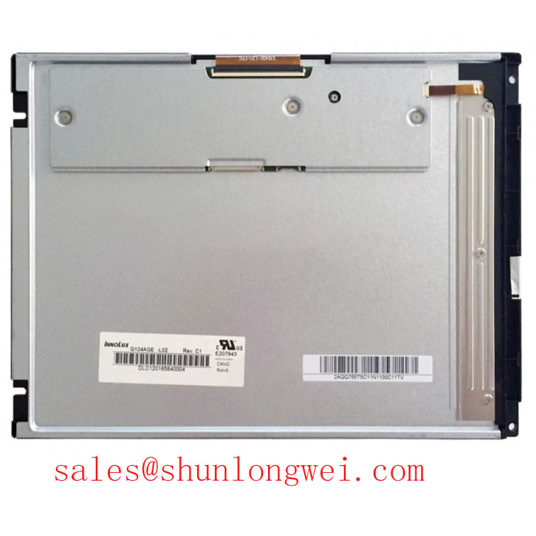
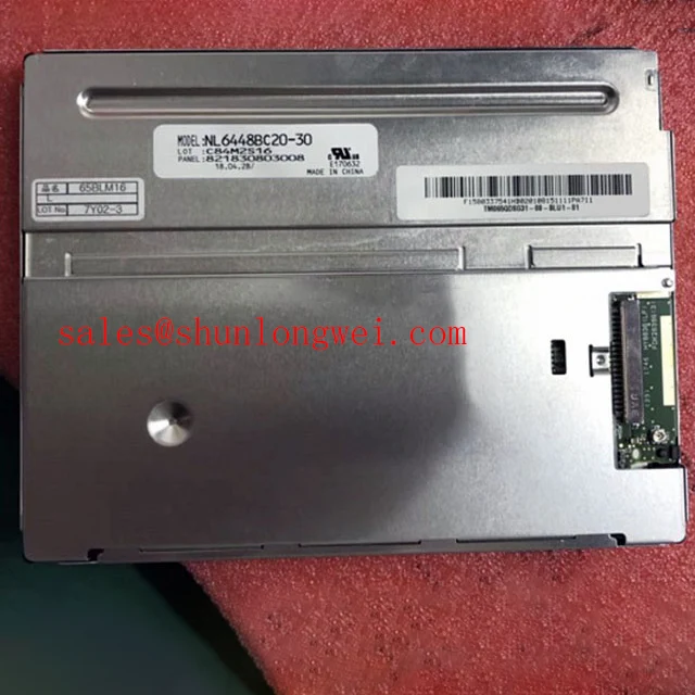
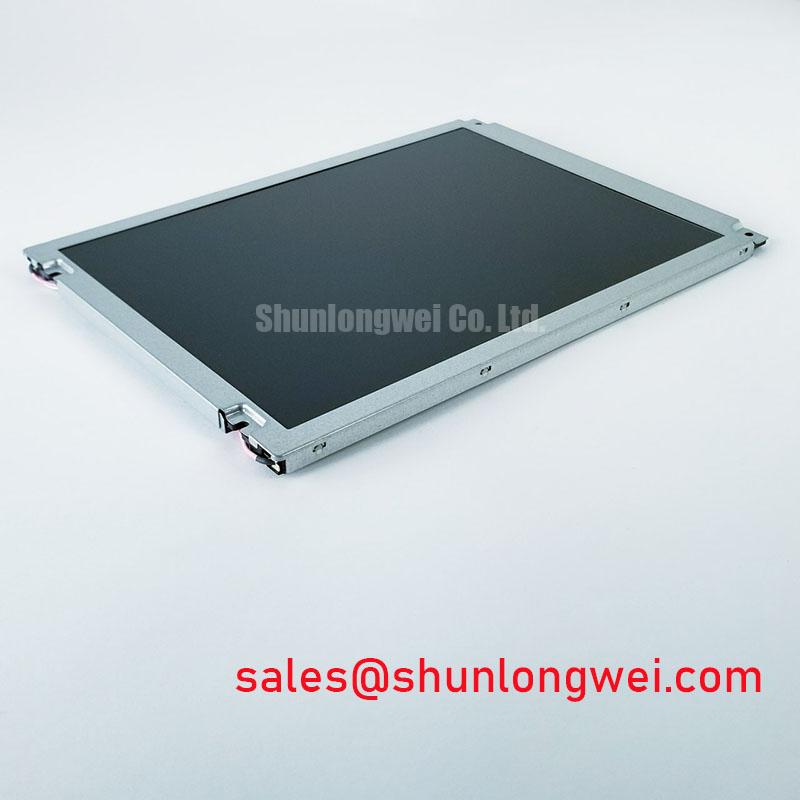
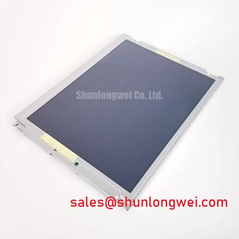
When a precision test instrument reports a blank screen, split image, or unstable color field, begin with the display connector seated and the panel supply isolated from the host controller. The TM104SDHG30-02 is a Tianma TFT-LCD Active Matrix Color Display Module identified for an Industrial Grade LCD/HMI Panel application. Its listed status is Decoded Baseline / Standard Form Factor, so the replacement assessment should begin with the original unit’s electrical interface and mechanical drawing rather than with the model number alone.
For a controller using a TTL RGB path, compare the installed signal naming with the original panel documentation before applying power. A 24-bit RGB bus normally requires consistent color-bit mapping, pixel clock polarity, display enable behavior, and synchronization timing. The system integrator should verify whether the host uses the expected 3.3 V or 5.0 V logic rail for the complete display assembly, then observe the power-on rise profile and reset relationship with an oscilloscope. These are system-level integration conditions, not confirmed electrical ratings for this display module.
TTL RGB wiring is generally single-ended, whereas JEIDA and VESA mapping terminology is commonly associated with LVDS interfaces. If the display chain uses LVDS rather than TTL RGB, mapping differences can produce color inversion, misplaced color channels, or a divided image even when the panel receives a stable supply. Check the transmitter configuration against the original signal path and compare clock, data, and enable timing at the panel connector. In an industrial cabinet, route high-speed display conductors away from switching-node wiring. Where the host interface is differential, preserve the controlled differential path specified by the system design. The stated 100 ohm differential target and skew limits in a system drawing should be treated as board-level design requirements, not as unqualified product specifications.
Clock jitter and data hold margin should be checked across the actual operating temperature range of the instrument. A display that works on a bench may show intermittent vertical bands after the cabinet warms up if connector retention, cable flexing, or transmitter timing has insufficient margin. For a same-size or same-resolution evaluation, engineers may compare the interface and mounting data of TX31D35VC1CAA, while retaining the original panel documentation as the controlling reference.
Flashlight Dark-Shadow Optical Diagnostic for Logic and Backlight Fault Separation
Separate image-generation faults from illumination faults before replacing the display assembly. A controlled bench test can use solid red, green, blue, white, and black screens generated by the host controller. Observe whether the image data changes correctly while the visible brightness remains uneven. This primary-color sequence helps distinguish a missing color channel or timing error from a problem in the illumination path.
With the display operating at a safe brightness level, place a flashlight at approximately 45 degrees to the front surface and inspect dark regions that remain visible under reflected light. A faint image beneath a dark field can indicate that the LCD is forming an image while the backlight path is inactive or uneven. By contrast, fixed lines, localized columns, or regions that react when the flexible connection is gently stabilized may point toward an interface or panel-driver issue. This observation is a diagnostic direction, not a single-cause confirmation.
Do not press the active area or bend the flexible tail during this test. Instead, inspect the connector latch, cable seating, and strain relief, then repeat the color sequence with a known-good signal source where available. High-EMI factory equipment benefits from controlled differential routing, consistent pair geometry, and a documented skew budget when the display interface is differential. A nominal 100 ohm differential path with a system-defined tolerance can be assessed using the host board and cable together; it should not be treated as an independent rating of the TM104SDHG30-02.
For a complete display chain, the host controller, panel interface, and illumination driver must be assessed as one electrical system. The related TX31D55VM2AAA may be reviewed as a separate display solution in the surrounding architecture, subject to connector, timing, and mechanical compatibility. Maintenance Note: Disconnect power before reseating the display cable, and inspect the connector lock during scheduled cabinet service.
Chassis M3 Fastener Loading and Optical Mura Control
Uneven bezel loading can create localized brightness variation even when the image signal is correct. Mount the panel against a clean, flat support surface and bring the fasteners into contact in a cross pattern so the bezel does not pull toward one corner. Use the equipment drawing or fastener specification to select an appropriate tightening torque; any value used for compatible chassis hardware is a general mechanical guideline, not a confirmed Tianma factory specification for this model.
Use the original equipment drawing to establish the panel cutout, bezel envelope, connector clearance, and support locations. Do not force a mounting hole into alignment by tightening the opposite corner. Mechanical stress can transfer through the bezel and frame, producing bright or dark patches that change with viewing angle or temperature. If the optical pattern changes when fasteners are loosened and retightened evenly, investigate the enclosure interface, gasket compression, and support flatness before changing the display electronics.
Thermal expansion also affects the mechanical interface. In a precision electronic test instrument, the display frame, front panel, and mounting bracket may not expand at the same rate. Designers should provide a controlled support scheme that restrains movement without concentrating load at isolated points. The enclosure gasket should remain continuous around the opening, while its compression and material suitability are determined by the equipment manufacturer’s mechanical design.
Flexible cables require a smooth bend path with no sharp fold at the connector exit. Allow the cable to move with the display assembly during vibration and thermal cycling, while preventing it from rubbing against a metal edge. Connector locking force, cable retention, and strain relief should be checked after installation and again following transport or service work. These practices support mechanical reliability without assigning an unverified flex-life or shock rating to the TM104SDHG30-02.
For background on panel selection, optical behavior, and integration terminology, consult The Ultimate Guide to Industrial TFT LCD Technology.
Backlight Driver and Cold-Ignition Debugging
Identify the installed illumination architecture before connecting a replacement driver. The TM104SDHG30-02 listing supplied for this page identifies the product as a TFT-LCD active matrix color display module, but it does not establish a universal CCFL or LED configuration in the available product parameters. The original panel documentation, connector pinout, and host inverter or driver assembly must determine the correct electrical path.
If the equipment uses a CCFL inverter, evaluate the cold-start sequence with suitable high-voltage probes and protective procedures. A failed ignition attempt, audible transformer noise, or repeated restart may originate in the inverter, lamp circuit, feedback loop, connector, or protection threshold rather than in the LCD image layer. Do not apply a stated ignition voltage as a default replacement setting unless it is confirmed by the original panel and inverter documentation.
If the equipment uses an LED driver, verify enable polarity, current regulation, dimming control, thermal behavior, and fault feedback at the system interface. PWM dimming performance belongs to the driver and controller combination, so a claimed dimming ratio or service-life figure should not be assigned to this display module without a manufacturer source and defined test conditions. Brightness decay, temperature, drive current, and enclosure airflow all influence the observed service behavior.
Acoustic buzz should be investigated by correlating the sound with driver switching, mechanical resonance, and brightness commands. Check the driver mounting, cable routing, and supply stability while observing the display for flicker or intermittent restart. Tianma’s industrial display resources at Tianma NLT Industrial TFT-LCD Display Technologies and Tianma Microelectronics Industrial TFT Displays provide useful manufacturer-level context for industrial display technologies, while the exact replacement interface remains governed by the original assembly documentation.