Content last revised on October 13, 2026
Chassis Fastener Torque Sizing to Reduce Optical Mura Defects
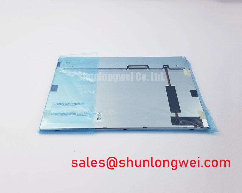
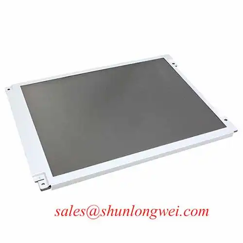
I check whether the enclosure supports the display frame evenly before treating a dark patch as a panel fault. For the TM104SDHG40, the mounting assessment should compare the module drawing with the bezel opening, support surfaces, connector clearance, and assembled gasket compression. A housing that contacts the viewing area or twists the frame can introduce optical nonuniformity without an electrical fault.
Design Consideration: inspect the display with uniform dark and intermediate-gray images while comparing its supported, uncompressed condition with the assembled condition. Record whether the pattern changes with enclosure pressure, viewing direction, or warm-up. Such changes help distinguish mounting sensitivity from illumination variation; they do not establish a single cause. Fastener size and tightening torque belong to the approved mechanical stack, not to an assumed universal LCD mounting rule. Where the chassis uses M3 fasteners, determine torque from the actual joint, insert, and frame requirements.
A cross-pattern tightening sequence can help distribute loading, provided the mounting arrangement permits it. Check the complete tolerance stack rather than only the nominal opening: bracket alignment, gasket thickness, enclosure flatness, and cable exit position all influence the assembled fit. Optical bonding is a separate integration decision. Adhesive compatibility, cure stress, edge sealing, and rework access require assembly-level qualification; bonding alone does not establish moisture resistance or enclosure airtightness.
For sourcing comparisons, TX31D11VC1CAA provides another display product to evaluate, not an established interchangeable replacement. Compare documented active area, outline dimensions, mounting points, interface definition, and optical requirements before approving either module for the same enclosure.
Suppressing Pixel Jitter and Horizontal White Lines Near Motor Drives
Correlate intermittent pixel disturbance with drive switching and cable position before changing the display controller. A nearby motor drive can introduce conducted or radiated interference, but horizontal lines can also originate from timing errors, connector contact problems, or unstable power. Design Consideration: compare the receiver-side waveform and supply behavior with a known-good operating condition while changing one installation variable at a time.
The interface drawing should govern cable construction and controller configuration. For an LVDS signal path, evaluate differential-pair continuity, impedance discontinuities, clock quality, and the receiver’s supported data mapping. JEIDA and VESA mapping must match where that distinction applies. For a documented parallel interface, assess clock-to-data relationships and setup and hold timing instead. These are different verification paths, not evidence that TM104SDHG40 accepts both interfaces.
Shield termination should follow the equipment grounding architecture. Broad circumferential termination can reduce high-frequency coupling in a shielded cable assembly, but its effectiveness depends on connector construction and chassis continuity. A common-mode suppression component is an optional system measure requiring signal-integrity evaluation, not a standard accessory for this module. Repeat timing checks across the equipment’s qualified temperature conditions, accounting for transmitter drift, cable loading, and receiver limits.
Pro Tip: Where the documented interface uses differential pairs, maintain pair symmetry through routing and connectors, then verify receiver-side timing rather than relying on trace length alone.
Inspect the flexible cable’s supported bend path and connector latch engagement without assigning an unsupported bend-life rating. Avoid transferring cable tension into the connector when the enclosure closes. During power-sequence checks, capture panel power, interface activity, and backlight enable together; compare their order with the specified sequence. A white screen or residual image during shutdown is a diagnostic observation, not proof of a failed panel.
Contrast Stability and Liquid Crystal Temperature Tracking
Compare grayscale visibility at the intended operator position before adjusting contrast or backlight settings. Design Consideration: use the same test image, viewing geometry, ambient illumination, and controller configuration when assessing the TM104SDHG40. Liquid-crystal response and optical appearance can change with temperature, while cover-glass reflections can reduce perceived contrast independently of the panel’s electrical operation.
Do not infer a TN, IPS, or MVA optical structure from the product name. Those technologies have different viewing characteristics, but symmetric viewing-angle limits, anti-glare treatment, and sunlight contrast require model-specific optical specifications. The manufacturer’s Tianma NLT Industrial TFT-LCD Display Technologies and Tianma Microelectronics Industrial TFT Displays resources provide broader technology context; their general descriptions are not individual TM104SDHG40 ratings.
When evaluating railway passenger information equipment or a cab signalling display, assess legibility through the finished cover assembly and at the actual installation angle. This is a compatibility assessment, not a declaration of railway qualification. Anti-glare surfaces can change reflection distribution, while bonding can alter optical interfaces; evaluate the finished assembly rather than transferring bare-panel measurements directly to the enclosure.
For persistent HMI graphics, consider interface layouts that periodically change static content where operational requirements allow. If image retention appears, compare its persistence after changing the image and under controlled temperature conditions. Separate retention from controller artifacts and illumination nonuniformity before deciding on replacement. The Ultimate Guide to Industrial TFT LCD Technology provides supporting terminology for these checks.
Reducing Localized Thermal Gradients and Investigating Color Shift
Map enclosure temperatures alongside brightness and color uniformity after the display reaches a stable operating condition. Design Consideration: compare edge heating, nearby power components, airflow restrictions, and bracket contact with the observed optical pattern. Local temperature differences can affect appearance, but discoloration alone does not identify an internal material or establish irreversible damage.
A heat-spreading bracket should distribute heat without imposing frame distortion or obstructing cable access. Its material, contact arrangement, and dimensions should follow the enclosure thermal analysis and mechanical validation. Do not attribute a particular light-guide material, backlight lifetime, or brightness-maintenance classification to this model without supporting manufacturer data.
For a documented LED backlight configuration, evaluate the specified current regulation, enable sequence, and supported dimming method against the selected driver. PWM behavior should be checked for visible modulation and acoustic effects over the required brightness range; a generic frequency range is not a module specification. The TX17D02VM2CAA-2 display can serve as a separate power-interface comparison, not as a backlight driver or an assumed companion component.
After thermal or power-path changes, repeat brightness-uniformity checks with unchanged image settings and measurement geometry. Record actual driver behavior and enclosure temperatures so subsequent maintenance can distinguish a changed operating condition from a developing display fault.