Content last revised on October 8, 2026
Checking Display Signal Routing and Cable Connections
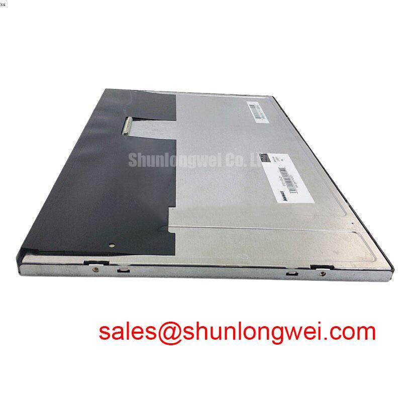
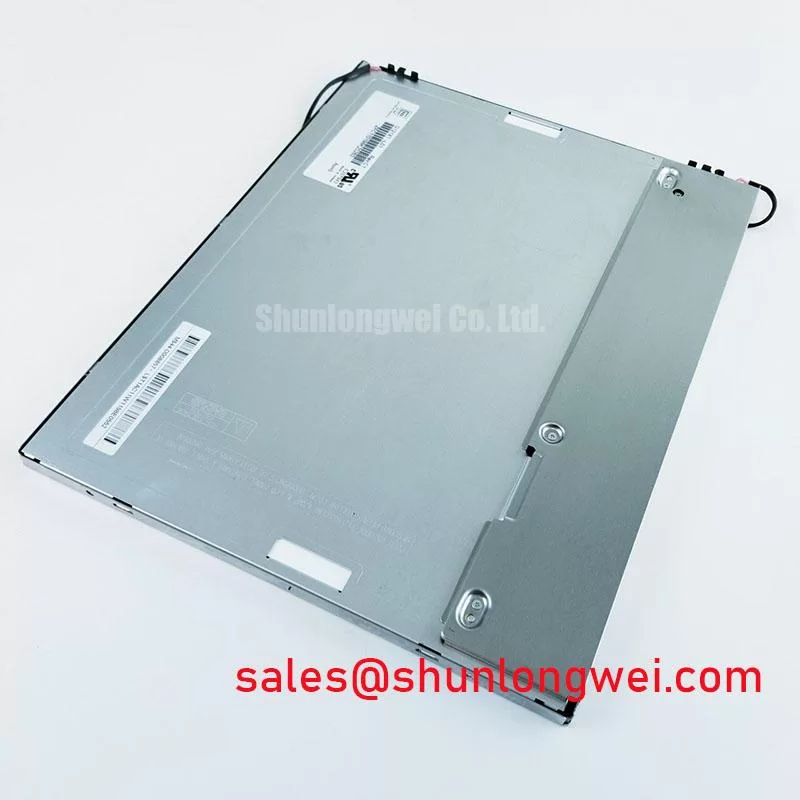
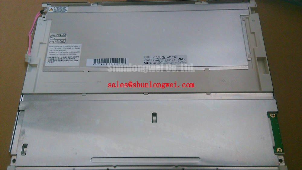
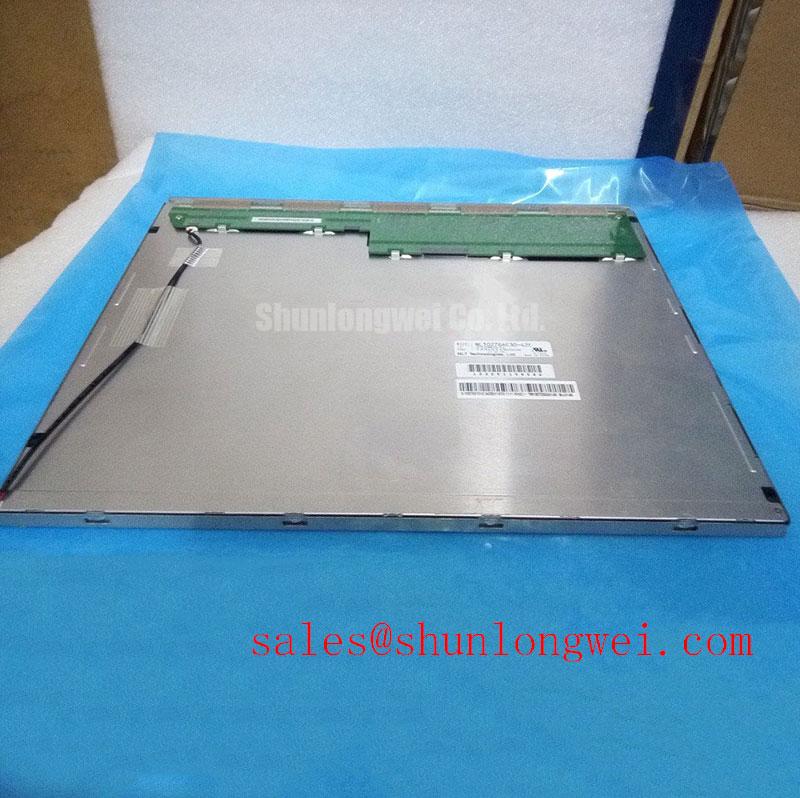
With the operator station isolated from power, compare the label on the removed display with AA121TD11-DE1 before disconnecting its signal cable. This Mitsubishi Electric TFT-LCD display module is an industrial LCD/HMI panel, but a matching model label alone does not establish that the surrounding petrochemical Zone 2 operator station retains its required protection. Record the existing cable orientation, mounting arrangement and enclosure condition before bench testing.
Begin at the host connector, not at an assumed interface standard. Identify the supply and signal pins from the applicable original panel and equipment documentation, then measure the host supply during startup with the display connected. The available product information identifies AA121TD11-DE1 as a TFT-LCD display module; it does not establish a supply voltage, connector pinout, interface type or power-on timing limit. Do not apply a presumed logic voltage or use a timing figure borrowed from another panel.
If the original documentation confirms an LVDS connection, controlled differential routing becomes a Design Consideration for the host board and cable assembly. Compare the installed cable with the equipment schematic: check pair assignment, polarity, shielding and continuity before attributing a split image to the LCD. A nominal differential impedance target is useful only when it comes from the confirmed interface design; it is not an official specification for this module in the information available here. Inspect the connector under magnification for displaced contacts or a flex cable seated at an angle, then observe the clock and data signals at accessible test points using suitable probing.
Color bands, swapped tones or a split-screen image can also arise from a mismatch between the host’s transmitted pixel mapping and the panel’s expected mapping. Verify that mapping against the original documentation rather than changing JEIDA or VESA settings by trial and error. In a petrochemical operator station, conduct signal checks on an appropriately isolated bench; any return-to-service decision must also follow the equipment maker’s instructions for the complete protected assembly.
Checking Display Lines and Mechanical Stress
Run a full-screen primary-color inspection with the panel supported flat in a suitable test fixture. Show red, green and blue fields in sequence, viewing each from the normal operator position before moving closer to record individual pixel defects. Follow with uniform light and dark fields to reveal lines and uneven illumination that a detailed HMI screen can conceal. Keep the test image, viewing position and camera exposure consistent when comparing this unit with a known-good display.
A persistent vertical line is evidence to investigate, not proof of a particular bond or driver failure. First confirm that the source image is clean and the cable is fully seated. Then check whether the line remains fixed across the color fields and whether it appears on a known-good signal path. Avoid pressing the glass or twisting its mounting frame to see whether the line changes: that action can introduce stress while offering little diagnostic certainty. Examine the glass perimeter and accessible driver-connection area for visible damage without disturbing bonded parts.
For a dark patch, view the unpowered surface under a flashlight held at an oblique angle, then compare that location with the illuminated test image. Reflections and surface marks may become visible in the oblique view, while an illumination fault may present differently when the backlight is on. Neither observation alone isolates the cause. Measure the backlight input and inspect its connection using the original equipment documentation before deciding whether the display or its external drive circuitry needs further testing.
💡 Bench Tip: Wear an ESD wrist strap and support the flex cable near its connector whenever the panel is repositioned.
Assessing Surface Reflections and High Ambient Readability
Assess the installed viewing stack before assigning an optical feature to AA121TD11-DE1. The information available here does not confirm an etched anti-glare surface, an anti-reflective coating, a contrast ratio or a sunlight-readability rating for this model. The operator-station cover window can also dominate what a technician sees: fingerprints, scratches and reflected task lighting may reduce readability even when the LCD image itself is stable.
Photograph the same test pattern with the cover window in its normal position and, where the equipment procedure permits, with the display assessed separately on the bench. Note the light direction and viewing angle. Diffuse reflections, mirror-like glare and a washed-out image call for different checks; none establishes the panel’s coating type. Use only cleaning materials approved for the documented display and window surfaces, since an undocumented treatment should not be assumed to tolerate a particular solvent or abrasive method.
Check grayscale and color from the positions an operator actually uses. An image that changes strongly with viewing angle may reflect the panel’s display mode, the mounting angle or the cover-window optics. The available product information does not identify this model as TN, IPS or MVA, and it provides no viewing-cone figure. For a cross-model evaluation, AA104VC01 can be examined as a separate product reference, not a confirmed drop-in replacement. Compare its documented active area, resolution, interface, supply, mechanical envelope and optical behavior against the original equipment requirements before drawing a substitution decision.
Checking Image Response in Cold and Outdoor Industrial Conditions
At low temperature, liquid-crystal response can slow, so a moving status graphic may smear even while a static alarm remains legible. Test the actual operator interface at the temperatures specified for the complete equipment; do not assign the panel a cold-start or thermal-cycle rating without its applicable factory documentation. Display moving edges and changing numerals alongside a static reference. Record whether the host continues to update correctly, since a stalled source can resemble a slow display.
Check startup and shutdown separately. If the documented interface is LVDS, examine clock and data behavior at the installed cable length and through the equipment’s operating conditions; if it is another interface, use that interface’s documented timing requirements instead. Compare observations with the host and panel specifications rather than imposing a generic jitter or hold-time budget. Likewise, determine the approved backlight supply and control method before changing dimming settings. Visible flicker, uneven brightness and delayed illumination warrant separate checks of the panel connection, the external backlight drive and the source image.
After temperature exposure, inspect the mounting frame, gasket contact and cable strain relief for changes that could load the glass or loosen a connector. Do not treat a proposed thermal range, seal construction or backlight lifetime as a rating for AA121TD11-DE1 unless the applicable factory specification states it. For the Zone 2 station, the enclosure, wiring method and return-to-service procedure remain system-level matters; Industrial Display & HMI Solutions provides additional context for organizing display checks under harsh operating conditions.