Content last revised on September 26, 2026
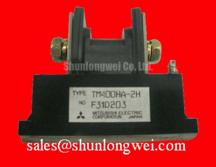
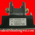
TM400HA-2H Mitsubishi Electric 1000 V 400 A Thyristor Module
Begin incoming inspection by isolating the TM400HA-2H from every external circuit, checking the housing for cracks or deformation, and confirming the marked terminals against the equipment wiring before applying any test voltage. The available factory hardware data identifies this Mitsubishi Electric device as a Thyristor Module with an official rated voltage of 1000.0 V, an official rated current of 400.0 A, and an Isolated Power Module package.
For a replacement evaluation in a medium-frequency induction melting or metal hardening power supply, these three values establish the first compatibility screen. They do not, by themselves, confirm suitability for a particular firing circuit, cooling arrangement, surge environment, semiconductor fuse, or operating waveform. The system integrator should verify the original equipment documentation and the complete Mitsubishi Electric data sheet before energizing the assembly.
| Manufacturer | Mitsubishi Electric |
| Part number | TM400HA-2H |
| Product category | Thyristor Module |
| Official rated voltage | 1000.0 V |
| Official rated current | 400.0 A |
| Package | Isolated Power Module |
The isolated package is relevant when the module is installed on a heat-spreading structure that may be connected to protective earth or another chassis reference. The isolation rating, creepage distance, clearance, terminal arrangement, gate characteristics, thermal resistance, surge current capability, and recommended mounting method are not included in the supplied parameter set. Those values must be taken from the applicable Mitsubishi Electric documentation rather than inferred from the 1000 V and 400 A ratings.
💡 Bench Tip: Use ESD precautions and record a cold-state reference for each accessible terminal relationship before comparing the unit with a known-good assembly.
Preventing Spurious Faults: IEEE 61000-4-5 Industrial Surge Immunity: Guidelines for TM400HA-2H
When a TM400HA-2H is evaluated for an induction melting or hardening furnace, the AC input protection network should be reviewed as part of the complete power converter rather than as an attribute of the thyristor module alone. IEEE 61000-4-5 may be used as a system-level surge-immunity reference, but the module itself should not be described as independently certified to that standard. The protection design normally requires coordination among the upstream disconnect, semiconductor protection fuse, surge suppression, control transformer, firing board, and the power terminals.
An MOV network can provide a path for transient energy, while an RC snubber may reduce the rate of voltage change seen by a thyristor junction. The correct MOV voltage class, energy capability, repetitive duty, and failure mode depend on the actual line voltage, connection arrangement, source impedance, prospective fault current, and surge test level. These are system-determined values. Designers should select and validate the network using measured line transients and the applicable protection documentation instead of assigning an MOV rating from the module’s 1000.0 V figure alone.
The same limitation applies to RC snubber selection. The resistance, capacitance, pulse rating, damping behavior, and physical loop must be checked against the converter’s commutation behavior and firing arrangement. A snubber that is acceptable in a laboratory rectifier may produce unwanted reactive current or excessive component heating in a high-power induction furnace. Oscilloscope measurements should be taken at the module terminals with suitable high-voltage probes, observing both the switching waveform and the control reference.
The supplied factory information does not provide a fuse I²t coordination table, surge-current curve, repetitive peak off-state voltage, critical rate-of-rise information, or terminal torque specification. These omissions are important during a surge review. A procurement or maintenance team should request the applicable technical document before approving a protection assembly, especially where the existing equipment has experienced nuisance triggering, repeated fuse operation, or visible damage around the power connections.
Keep the high-current conductors physically short and arranged to limit the area of the commutation loop. This is a Design Consideration, not a published TM400HA-2H dimensional requirement. The final layout should be verified by measurement during controlled switching tests, with peak terminal voltage compared against the documented device limits and the DC-link or AC-line conditions of the furnace.
Assembly Integrity & Layout Architecture: Evaluating Post-Surge Reverse-Voltage Blocking for TM400HA-2H
Post-surge inspection should start with the external assembly. Disconnect the source, wait for the equipment discharge procedure to complete, and inspect the isolated power module, bus bars, cable lugs, insulating barriers, and mounting surface. Look for carbon tracking, loosened hardware, discoloration, cracked insulation, and contamination near the power terminals. These observations do not identify a single failure mechanism, but they help determine whether the next test should focus on insulation, gate control, commutation, or mechanical integrity.
A reverse-voltage blocking review requires the engineer to confirm the actual circuit topology. The TM400HA-2H is identified in the supplied data as a 1000.0 V, 400.0 A thyristor module, but no official ITSM value or 10 ms half-cycle surge-current rating has been provided here. Consequently, a post-surge withstand decision must not be based on a guessed surge rating. The applicable manufacturer curve should be checked for non-repetitive surge current, peak junction temperature, pulse duration, initial junction condition, and recovery requirements.
In a phase-controlled rectifier, reverse voltage can reappear across a device after current commutation or an abnormal firing event. The protection review should therefore compare the measured reverse-voltage waveform with the documented repetitive and non-repetitive voltage limits. Engineers should also verify whether the firing board maintains a defined off-state during supply disturbances. A control signal that appears correct at the controller output may still be exposed to common-mode ground movement at the module gate and cathode references.
High-voltage insulation needs a physical review of creepage and clearance around the power terminals. The required distances depend on working voltage, pollution environment, material group, altitude, enclosure construction, and the relevant safety standard. Since no TM400HA-2H mechanical drawing or insulation coordination table is included in the supplied data, the system designer should not assign a universal distance. Instead, inspect the original approved layout and verify the installed spacing under the intended environmental conditions.
⚠️ Field Alert: Never reconnect a power or gate cable while the furnace converter is energized or while its DC-link discharge status has not been independently verified.
After a surge event, a static resistance or diode-mode reading can support an investigation, but it is not a substitute for the manufacturer’s dynamic test limits. Record the test instrument, polarity, ambient condition, and terminal combination, then compare the result with a known-good module of the same type. If the readings differ materially, continue with an isolation test and controlled gate-circuit examination only after confirming that the test voltage and current are appropriate for the device and the surrounding circuit.
TM400HA-2H Circuit Protection & Reliability: Calibrating Phase-Controlled Rectification, Firing Angle
The TM400HA-2H may be evaluated in a phase-controlled rectifier where the firing circuit adjusts the conduction interval supplied to a furnace converter. The requested firing-angle range from 0 degrees to 150 degrees is a system operating study, not an official operating range stated in the supplied factory parameters. At small firing angles, the converter can draw substantial real power and produce steep current transitions. At larger angles, average DC output generally decreases while the relationship between displacement, reactive current, load characteristics, and commutation behavior becomes increasingly important.
Engineers should measure the actual line voltage, phase current, gate timing, load current, and module terminal voltage at representative operating points. The purpose is to confirm that the applied waveform remains within the documented electrical limits and that the firing board does not create unintended simultaneous conduction or missed triggering. The 1000.0 V voltage rating and 400.0 A current rating are official device parameters, but they do not define the allowable RMS current for every cooling condition or firing-angle profile.
Gate wiring deserves particular attention in a high-current furnace. Keep gate and return conductors referenced according to the original circuit design, route them away from high di/dt power paths, and investigate common-mode ground bounce when the gate waveform appears unstable. A negative gate bias may be used in some system architectures, but no negative-bias voltage is specified in the supplied TM400HA-2H data. The correct gate drive voltage, pulse current, pulse width, isolation method, and off-state bias must therefore be verified from the module documentation and the firing-board design.
Do not use a general gate-emitter or gate-cathode measurement assumption from another semiconductor family. A thyristor gate circuit has its own trigger-current, holding-current, latching-current, and immunity requirements. The incoming technician can verify terminal identity and cold-state behavior, but dynamic trigger validation should be performed with a controlled low-energy test arrangement that protects the device and separates the gate circuit from the furnace power stage.
For a broader topology comparison, the neutral reference [SKT240/18E](https://www.slw-ele.com/skt240-18e.html) can be reviewed as another power semiconductor option, while [SKT340/18E](https://www.slw-ele.com/skt340-18e.html) may be considered in relation to a separate front-end or auxiliary rectification stage. These links do not establish interchangeability. Voltage class, current waveform, gate requirements, mechanical dimensions, isolation, thermal design, and protection coordination must be checked independently before any substitution decision.
Power factor and reactive demand should be assessed at the equipment input rather than inferred from the module label. Use synchronized voltage and current measurements across the firing-angle range, then evaluate transformer loading, line distortion, capacitor-bank interaction, and upstream protection response. Any correction equipment should be reviewed for resonance and transient interaction with the phase-controlled converter.
TM400HA-2H Operational Boundaries: Evaluating Semiconductor Protection Fuse Selection in Limits
Semiconductor fuse selection begins with the actual fault-clearing requirement, not simply the 400.0 A device rating. The engineer should identify the available short-circuit current, source impedance, conductor impedance, fuse class, prospective fault duration, peak let-through current, clearing time, and fuse I²t. The provided TM400HA-2H parameters do not include a fuse coordination table, a device I²t withstand value, or a published short-circuit protection combination, so a guaranteed dead-short protection claim cannot be made from the available information.
During a design review, compare the fuse manufacturer’s total clearing I²t with the applicable thyristor non-repetitive surge withstand data at the relevant starting junction temperature. This is an Engineering Calculation that requires verified manufacturer curves and the actual fault waveform. It should also account for asymmetrical current, supply frequency, line inductance, multiple parallel paths, and the possibility that one phase clears before another. A nominal fuse current marking alone is insufficient evidence of coordination.
Inspect fuse connections, bus-bar support, pressure contacts, and the physical distance between the fuse and module terminals. Excessive connection impedance can alter fault current and generate local heating, while a poorly supported conductor can impose mechanical stress during a high-current event. The appropriate mounting torque must come from the Mitsubishi Electric mechanical documentation and the selected fuse manufacturer’s instructions; it should not be inferred from the isolated package description.
The final protection validation should use a documented test plan covering normal firing, blocked firing, supply interruption, restart behavior, and controlled fault conditions where permitted by the equipment owner and safety procedures. Record the gate waveform, line current, fuse clearing behavior, terminal voltage, and post-test insulation condition. If the furnace application is being updated with wide-bandgap devices elsewhere in the converter, the switching behavior and protection coordination should be reassessed rather than assumed equivalent; the general technology background is discussed in [Wide Bandgap Revolution](https://www.slw-ele.com/topic/wide-bandgap-revolution-core-advantages-and-design-challenges-of-gan-and-sic-power-semiconductors).
For procurement and repair records, identify the unit as Mitsubishi Electric TM400HA-2H, a 1000.0 V, 400.0 A isolated thyristor module. Before installation, match the original terminal arrangement, heat-transfer interface, insulation scheme, gate-control circuit, fuse coordination, and approved enclosure layout. Where any of those records are unavailable, the replacement should remain unenergized until the missing limits have been confirmed from the applicable manufacturer documentation and validated by the responsible system engineer.