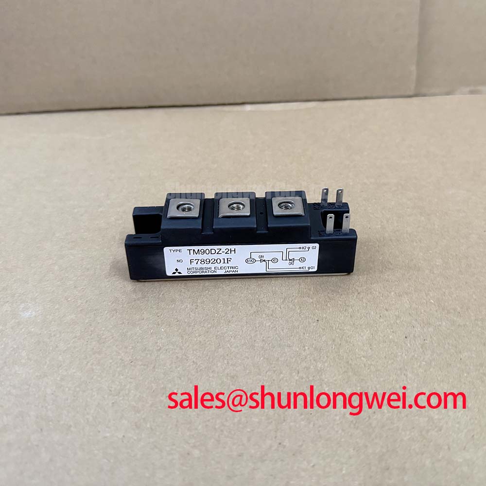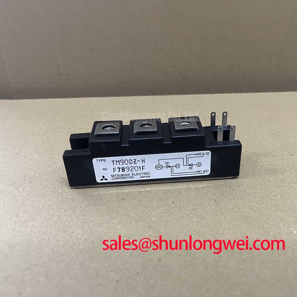


Content last revised on October 6, 2026
Assembly Integrity and Layout Architecture for TM90DZ-H
| Parameter | Official specification |
|---|---|
| Manufacturer | Mitsubishi Electric |
| Model | TM90DZ-H |
| Product category | Thyristor Module |
| Rated voltage | 800.0 V |
| Rated current | 90.0 A |
| Package | Isolated Power Module |
For a grid tied static Var compensator or thyristor switched capacitor assembly, inspect the power terminals, mounting surface, insulating hardware, and conductor routing before applying operating voltage. The 800.0 V rating should be compared with the actual line voltage, transient environment, commutation condition, and the required clearance and creepage of the complete assembly. The module rating alone does not establish the insulation capability of the finished cabinet.
Type 2 coordination between a semiconductor fuse and the thyristor module requires the fuse clearing characteristic and I²t value to be checked against the applicable TM90DZ-H data. The supplied product information does not include a fuse coordination table, surge withstand value, or detailed terminal map, so these values should be taken from the applicable Mitsubishi Electric documentation before protection is selected. A 90.0 A current rating must not be treated as a fuse sizing instruction.
Keep high current paths short and symmetrical, particularly where multiple phases share a laminated busbar or common capacitor bank. Separate control wiring from the power path and verify that the terminal labels match the original circuit drawing. When a neutral or auxiliary gate connection is present in the equipment, the system integrator should confirm its function from the original module documentation rather than infer it from physical position.
Pro Tip: Tighten the mounting hardware only to the torque specified by the applicable Mitsubishi Electric mechanical documentation, and verify the completed assembly with an insulation test suitable for the system voltage.
Benchtop Waveform Tuning for Sinusoidal Half Cycle Surge Conditions
Bench testing should begin with a current limited and isolated test arrangement. For SVC or thyristor switched capacitor service, observe the gate command, anode to cathode voltage, load current, and capacitor voltage together. This helps determine whether the device receives a clean firing command and whether reverse voltage is reapplied after current transfer.
The product data supplied here confirms the rated voltage and current, but does not provide an official ITSM surge current value, surge duration, junction temperature limit, or reverse recovery specification. These parameters must be verified in the correct manufacturer datasheet before any sinusoidal half cycle surge claim is made. Do not derive a permissible surge current from the 90.0 A continuous rating.
During waveform review, look for delayed triggering, uneven phase conduction, excessive ringing, or a voltage waveform that does not return to the expected commutation state. Such observations may indicate a gate drive, wiring, snubber, measurement, or load interaction issue. Compare each phase with a known good channel and use an appropriately rated differential probe.
The neutral comparison point for this module is its documented electrical boundary, not a generic thyristor waveform. Designers should verify peak voltage and current margins against the actual SVC operating profile during controlled switching tests.
Thermal Electrical Optimization and Gate Trigger Practice
Install the isolated power module on a clean, flat thermal interface and ensure that the heatsink contact area is free from burrs, contamination, and excessive surface irregularity. The available official data identifies the package as an isolated power module, but does not specify thermal resistance, allowable junction temperature, baseplate dimensions, or thermal interface material thickness. Those details must be confirmed before calculating heatsink performance.
Gate firing quality should be assessed at operating temperature, not only on a cold bench. Check pulse consistency, gate return routing, phase synchronization, and the effect of nearby power conductors. A short, low impedance gate loop is a general design consideration for limiting unwanted coupling, while the actual pulse current, pulse width, firing rate, and any multi pulse method remain system determined and must follow the applicable manufacturer documentation.
When the module is used in a capacitor switching branch, coordinate the firing command with the measured capacitor voltage and the intended commutation state. If the waveform differs between phases, inspect the complete gate circuit and its reference connections before attributing the condition to the thyristor itself. The related SKT240/18E may be evaluated as a separate device within a related power conversion topology, subject to its own specifications.
AC to DC Transfer Characteristics and Firing Angle Evaluation
Although the TM90DZ-H is a thyristor module rather than a complete converter, its switching behavior can influence the voltage, current, power factor, and reactive power profile of an AC controlled system. For a grid tied SVC, evaluate each firing angle using synchronized voltage and current measurements while monitoring the thermal condition of the module and the capacitor or reactor branch.
The requested firing angle range and any resulting transfer characteristic require the actual circuit configuration, line frequency, source impedance, load arrangement, commutation method, and control algorithm. These results should therefore be calculated from the system schematic and validated with measured waveforms. The 800.0 V and 90.0 A official ratings are boundary data for component selection, not a complete AC to DC transfer curve.
Review the displacement between voltage and current, current distortion, phase balance, and transient voltage at each switching event. Minimize parasitic loop inductance where practical to reduce switching overshoot, then verify the measured peak against the module voltage rating and the protection response. For a broader technology context, engineers may consult Future of Power Electronics.
Where a technically similar device is being assessed for a separate design, the SSIL2890S46C should be compared through its own official voltage, current, gate, thermal, and mechanical data rather than treated as an automatic substitute for TM90DZ-H.