Content last revised on September 17, 2026
Transient Dynamics & Electrical Design: Reverse Recovery Charge on TT250N12KOF
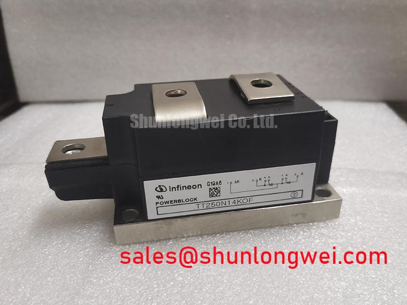
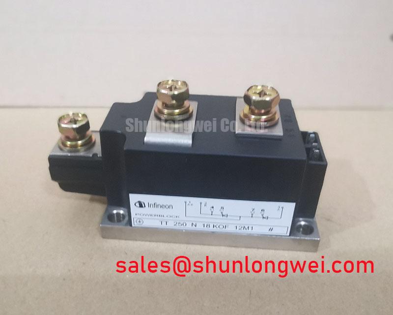
With the unit isolated from all energy sources, first verify terminal identification against the original equipment drawing and compare cold-state terminal readings across both thyristor paths before connecting the TT250N12KOF to a test fixture. This Infineon dual thyristor module is officially rated at 1200 V VDRM/VRRM, with an average on-state current of 250 A at case temperature of 85°C. Its 555 A RMS on-state current rating is specified at a 70°C case temperature. These values establish the electrical boundary that a replacement or repair evaluation should preserve.
The controlled thyristor paths should be assessed within the complete commutation circuit rather than treated as independent low-frequency switches. The supplied official data identifies the voltage and current ratings, but does not state reverse-recovery peak current, reverse-recovery charge, or recovery time for the thyristor paths. Those characteristics should therefore not be estimated as TT250N12KOF factory specifications. When reviewing an existing thyristor-switched capacitor or grid-tied static var compensator assembly, engineers should capture the commutation waveform with suitable isolated measurement equipment and compare it with the original system performance criteria.
A Design Consideration is to inspect the coordination of the MOV surge-clamping network, capacitor-bank inductance, busbar routing, and firing-circuit isolation. These external elements influence the transient voltage seen at the module terminals during switching. The objective is to minimize parasitic loop inductance where it can contribute to turn-off overshoot, then verify measured peak voltage against the 1200 V repetitive off-state rating during controlled switching tests.
Industrial drive boards frequently use optocouplers or digital isolators between the controller and thyristor trigger circuitry. Their common-mode transient capability, gate pulse integrity, and reference routing should be reviewed at the assembly level. Terminal creepage and clearance must also remain consistent with the equipment insulation design, particularly where busbars, MOV leads, or capacitor connections have been replaced.
💡 Bench Tip: Keep electrostatic protection in place and record cold-state diode-mode readings before and after fixture testing, since comparative readings are more useful than an unsupported universal pass or fail value.
Benchtop Waveform Tuning: Mitigating Stress via Fuse Total Clearing I2t versus Device Melt on TT250N12KOF
Fuse selection cannot be completed from the published TT250N12KOF ratings alone. The provided factory data includes a non-repetitive surge capability of 11.3 kA for a 60 Hz, 10 ms event, but does not provide a device melt I2t figure or a fuse coordination table. A semiconductor fuse total-clearing I2t value should consequently be checked against the original equipment documentation and the fuse manufacturer’s time-current and clearing-energy curves, not inferred from the surge-current number.
During a controlled fault-review exercise, inspect the fuse position relative to the protected thyristor branch, the integrity of terminal hardware, and the condition of the interconnecting conductors. A fuse that clears after a branch has experienced excessive energy may not prevent module damage, while an excessively sensitive fuse can compromise normal capacitor-bank switching. This is an Engineering Recommendation: evaluate prospective fault current, available source impedance, coordination curves, and actual enclosure wiring together before approving a substitute fuse.
The TT570N16 can serve as a neutral reference point when documenting a higher-current, higher-voltage module family for an engineering comparison. It should not be treated as a direct replacement without confirming topology, mounting interface, trigger requirements, thermal arrangement, and protection coordination.
Benchtop Waveform Tuning: Mitigating Stress via Sinusoidal 10 ms Half-Cycle Surge Current on TT250N12KOF
The official non-repetitive on-state surge rating is 11.3 kA at 60 Hz for 10 ms. This rating describes a defined short-duration event and is not a continuous operating-current value or a repeated fault allowance. For normal conduction assessment, use the official 250 A ITAVM rating at 85°C case temperature and 555 A ITRMS at 70°C case temperature as the applicable published limits.
Where an SVC or thyristor-switched capacitor bank has experienced a transient event, capture line current and device voltage before reapplying repetitive reverse voltage. An abnormal waveform can arise from several interacting conditions, including capacitor-bank imbalance, trigger timing variation, MOV condition, fuse coordination, or external insulation stress. The system integrator should verify whether the waveform remains within the original equipment limits and whether both thyristor paths show comparable cold-state behavior.
For broader context on power-semiconductor switching mechanisms and diagnostic terminology, consult The Ultimate IGBT Knowledge Base. Although the TT250N12KOF is a thyristor module rather than an IGBT module, disciplined voltage, current, thermal, and interconnect verification remains relevant to power-stage troubleshooting.
Field Diagnostics & Commissioning: Mechanical Mounting Torque Sequence and Thermal Considerations in TT250N12KOF Topologies
Thermal inspection begins at the case-to-heatsink interface. The TT250N12KOF has an official junction-to-case thermal resistance of 0.115 K/W per thyristor and a maximum junction temperature of 125°C. These ratings support thermal evaluation but do not define heatsink capability, thermal-interface thickness, mounting torque, or permissible case-temperature rise for a particular installation. The original mechanical drawing and equipment service documentation should be used to confirm fastening hardware and torque requirements.
A Design Consideration is to tighten mounting hardware progressively in the prescribed sequence so contact pressure is distributed evenly across the module base. Inspect for flat, clean mating surfaces, controlled thermal-interface application, and absence of baseplate distortion. After commissioning, compare temperature trends between the two thyristor branches under equivalent operating conditions; a difference may warrant checks of firing behavior, conductor resistance, heatsink contact, and load balance.
For module-family context, Infineon’s PrimePACK™ module information and HybridPACK™ Drive information illustrate the importance of matching a power module to its intended electrical, thermal, and mechanical system context. They do not establish TT250N12KOF-specific installation ratings.