



Content last revised on September 17, 2026
Benchtop Waveform Tuning: Managing di/dt Stress via Gate Firing: Pulse Train Timing on TZ630N24KOF
On an isolated bench fixture, examine the gate to cathode firing waveform at the device terminals rather than only at the output of the firing board. Cable routing, common return impedance, and terminal hardware can reshape a pulse substantially between the controller and the pressure contact thyristor. The 250 mA IGT value is the official trigger current specification, but it should not be treated as a complete gate drive design prescription. Gate pulse amplitude, rise behavior, duration, repetition pattern, and source impedance remain system determined parameters that require verification against the original control circuit.
In phase controlled motor soft starters, a multi pulse firing train is often assessed where a single gate pulse could be affected by line disturbance, circuit noise, or an uncertain conduction transition. This is a Design Consideration, not a factory mandated firing method for TZ630N24KOF. The commissioning engineer should observe anode current and gate current together across the intended firing angle range, particularly during low speed ramp conditions and uneven phase loading. A stable gate waveform alone does not prove appropriate operation if the main current waveform shows delayed or asymmetrical conduction.
Pay close attention to the return path used by the gate circuit. A thyristor gate loop should remain physically separated from high current power paths where practical, because shared inductance and shared voltage drop can alter the effective gate to cathode signal during a steep current transition. Unlike an IGBT gate circuit, this device’s gate firing arrangement is for turn on control; normal turn off in an AC soft starter depends on circuit current reaching its natural commutation condition. The system integrator should verify that the control philosophy reflects this thyristor behavior.
💡 Pro Tip: Keep the gate return path paired closely with its gate lead and confirm firing stability using terminal level oscilloscope measurements before increasing load.
Do not assign a generic gate pulse rise rate, back porch current, or holding current to this model without the relevant official document. If localized heating, intermittent firing, or unequal phase conduction is observed, compare the gate waveform and line current with a known healthy channel, inspect the terminal interfaces, and verify the firing board reference point. These observations can identify a circuit interaction, but they do not establish a single cause without measurement.
TZ630N24KOF Operational Boundaries: Evaluating Saturable Reactor and Snubber Sizing to Protection Limits
The 2400 V VDRM rating establishes the repetitive off state voltage boundary for TZ630N24KOF. It does not eliminate the need to measure transient voltage at the device in the assembled soft starter. Commutation events, supply disturbances, inductive branch wiring, and reactor interactions can produce voltage excursions that are not represented by a nominal supply reading. Engineers should verify peak terminal voltage during representative switching tests and compare the measured result with the applicable device limits and system derating policy.
RC snubbers and series saturable reactors are Design Considerations used to manage transient stress. An RC network can reduce the rate and amplitude of voltage transition seen across a nonconducting thyristor, while a saturable reactor can shape current rise during the interval where uncontrolled di/dt could stress the silicon and its external connections. Their values cannot be derived from the published VDRM, ITAV, ITSM, and IGT figures alone. The final network must be determined from the AC supply characteristics, motor branch inductance, firing pattern, physical layout, and measured waveform response.
A layered, compact power path is useful where the objective is to minimize parasitic loop inductance and suppress transient overshoot. In a pressure contact assembly, busbar symmetry is also important because unequal path impedance can contribute to phase imbalance. Inspect the location of snubber components relative to the thyristor terminals and the return route of their connections. Long leads can reduce the practical effectiveness of a correctly selected snubber because the lead inductance becomes part of the transient loop.
Long motor cables deserve separate measurement when the soft starter feeds a remote motor. Cable transmission effects can cause reflected voltage events at the motor side, especially during fast transitions in the wider motor control system. The effect depends on cable construction, length, termination, and the switching behavior of connected equipment. The system engineer should validate both device terminal waveforms and motor terminal waveforms where the installation presents that condition.
For a related Infineon device family used in power switching applications, the discussion in Infineon’s TRENCHSTOP™ 5 technical article provides useful context on the importance of module layout and switching behavior. It concerns IGBT technology and must not be used to transfer IGBT gate drive or switching specifications to TZ630N24KOF.
TZ630N24KOF Thermal Electrical Optimization: Semiconductor Protection Fuse Selection in Practical Tuning
The official 25.5 kA ITSM surge current capability indicates short duration surge robustness, but it is not a substitute for coordinated semiconductor protection. A dead short fault involves the complete protection chain: source impedance, conductor impedance, fuse pre arcing behavior, fuse clearing behavior, contactor state, reactor response, and mechanical containment of the equipment. The available official information does not provide a device specific I²t withstand value, so a fuse selection cannot be declared correct from the present parameters alone.
As an Engineering Recommendation, obtain the original fuse coordination data for the equipment and compare the prospective fault current with the selected fuse time current and let through characteristics. The system engineer should check whether the protective device can interrupt the available fault energy before the thyristor, connected diodes, busbars, and adjacent assemblies exceed their documented limits. This is especially important in high voltage three phase motor solid state soft starters, where the line supply can deliver substantial fault energy before upstream protection reacts.
Thermal review should begin with measured operating current and the actual conduction pattern. The 630 A ITAV rating is the official average on state current rating, but phase angle control produces a current waveform that is different from continuous full cycle conduction. During a starting ramp, each phase can experience a changing conduction angle and harmonic content. The heat sink, clamping stack, airflow, ambient condition, and ramp profile all affect junction temperature. The 125 °C Tvj max rating is a maximum boundary, not a preferred operating target.
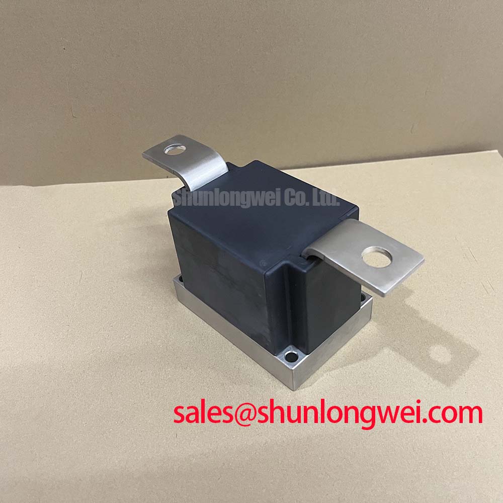
Inspect the pressure contact stack after any significant overcurrent event. Discoloration, uneven contact impressions, displaced hardware, or evidence of nonparallel seating should lead to a controlled mechanical review. The original manufacturer documentation should govern contact pressure and stack assembly requirements. Assigning a generic torque to this device would be inappropriate because a pressure contact arrangement is not equivalent to a stud mounted or screw terminal semiconductor package.
Where a repair assessment requires comparison with a lower voltage, lower current device, TD210N12 can be reviewed as a separate catalogued thyristor option. It is not an automatic electrical or mechanical substitute for TZ630N24KOF. Voltage class, average current capability, surge rating, contact geometry, firing circuit requirements, thermal stack compatibility, and protection coordination all require independent confirmation.
TZ630N24KOF Thermal Electrical Optimization: AC Input Transient Overvoltage Clamping and Practical Tuning
Begin AC input transient evaluation by recording the supply configuration, source transformer arrangement, cable entry path, line contactor behavior, and existing surge protection locations. A metal oxide varistor and an RC snubber can address different portions of the transient environment, but neither should be selected by applying a generic voltage number to a 2400 V VDRM thyristor. Their coordination must account for normal line voltage tolerance, expected surge exposure, protective device energy capability, and the clamping level measured at the semiconductor terminals.
IEC 61000-4-5 is commonly used as a system level surge immunity test framework. It does not certify an individual thyristor as compliant with equipment EMC or surge requirements. For this reason, the assembled soft starter should be evaluated with its enclosure, wiring, line filters, protective earth arrangement, and control electronics in place. The test plan and acceptance criteria remain the responsibility of the equipment designer or responsible integration team.
Place the transient protection discussion in the context of the complete topology. A related device such as TT570N16 may be evaluated within an associated rectifier or auxiliary power stage, but its presence does not define the correct clamping arrangement for TZ630N24KOF. Verify each device position, polarity, voltage rating, current path, and commutation role against the original schematic before any replacement work.
When unexplained trips or repeated protection events occur, capture line voltage, thyristor anode to cathode voltage, gate to cathode voltage, and phase current with properly rated isolated instrumentation. Look for timing correlation between the event and line switching, firing angle change, contactor action, or transient suppression activity. This approach can distinguish a supply transient, a firing synchronization issue, a wiring interaction, or a load side anomaly without asserting an unsupported single fault mechanism.
For structured measurement practice and fault isolation methods, consult the Field Engineer’s Handbook. Apply its workflow alongside the original equipment schematic and the applicable manufacturer documentation for the installed protection components.