

Content last revised on September 20, 2026
Benchtop Waveform Tuning: Mitigating Stress via Thermal Duty Cycle Management of Bypass Contactor Operation on TT61N16KOF-K
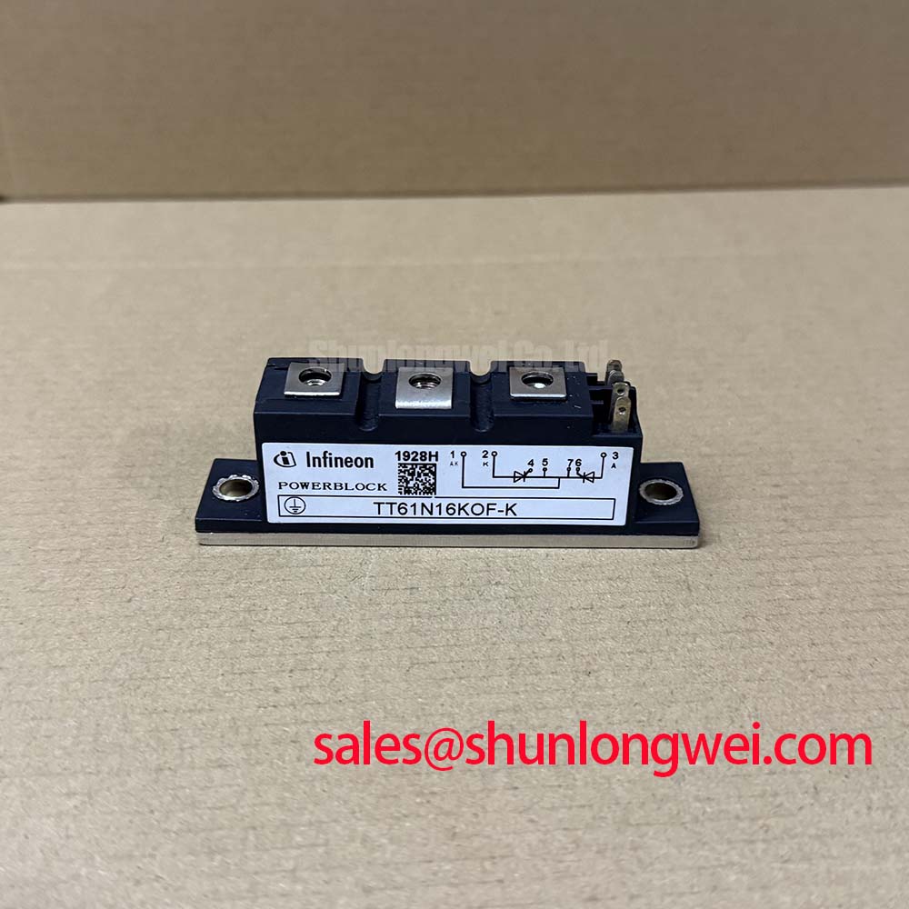
Before energizing a soft starter, verify the terminal connections against the equipment schematic, inspect the module mounting face for contamination or damage, and confirm that the nameplate electrical boundary matches the circuit requirement. The TT61N16KOF-K is an Infineon dual thyristor module with an official repetitive peak off state and reverse voltage rating of 1600 V. Its official average on state current rating is 60 A at Tc = 85 °C, while its RMS on state current rating is 95 A.
In a high voltage three phase motor solid state soft starter, paired thyristors control each AC phase during acceleration by changing the firing angle. The starter controller, motor characteristics, line impedance, bypass contactor sequence, and load inertia collectively determine the actual current profile. A controlled start may be assessed for its ability to reduce locked rotor current from the motor’s direct starting range, often cited as several times rated current, toward the system target. It is not a performance figure guaranteed by this module alone.
Design Consideration: bench measurements should capture phase current, line voltage, thyristor voltage, and heatsink temperature through the complete acceleration duty. Assess firing consistency between phases and check whether bypass transfer occurs only after the controller’s programmed conditions are met. Uneven triggering can raise thermal stress in one current path even where the commanded phase angle is identical.
The specified gate trigger current for this module is 150 mA. The gate drive circuit should be checked under its real isolation, noise, and temperature conditions to confirm dependable triggering without excessive gate current. Gate wiring should follow the original equipment connection arrangement, with short, controlled return paths that limit susceptibility to common mode disturbances.
| Official specification | Value |
|---|---|
| Repetitive peak off state / reverse voltage | 1600 V |
| Average on state current at case temperature | 60 A at Tc = 85 °C |
| RMS on state current | 95 A |
| Maximum junction temperature | 125 °C |
| Specified gate trigger current | 150 mA |
| Isolation test voltage | 3000 V RMS, 50 Hz, 1 min |
Assembly Integrity & Layout Architecture: Ensuring Uniform Heatsink Contact Pressure for TT61N16KOF-K
Clean the heatsink interface, examine the module baseplate seating area, and tighten mounting hardware in a balanced sequence specified by the original assembly documentation. The maximum junction temperature is 125 °C, so the thermal path from the module to the heatsink remains a primary integration check during repetitive starting duty.
Design Consideration: apply thermal interface material uniformly and avoid conditions that can tilt or distort the module during clamping. The correct mounting torque, screw type, washer arrangement, and tightening order must be verified from the original module and equipment documentation because these values are not established by the supplied official specifications.
⚡ Safety Interlock Note: Isolate and verify the complete power circuit is de energized before disconnecting gate, main terminal, or measurement wiring.
After installation, compare temperature distribution across the heatsink during a controlled load test. A local hot region can arise from interface contact, airflow, current imbalance, or a control issue, so it should be investigated with electrical and mechanical evidence rather than assigned to one cause. The module’s 3000 V RMS for 1 minute at 50 Hz isolation test specification is not a substitute for validating the insulation system of the complete starter.
TT61N16KOF-K Circuit Protection & Reliability: Calibrating Semiconductor Protection Fuse Selection in Motor Starter Assemblies
Review the existing fuse coordination record before replacing a thyristor module in a motor starter. The supplied official data identifies voltage, current, temperature, gate trigger, and isolation limits, but does not provide a module specific fuse I²t withstand value. A semiconductor fuse cannot therefore be selected from the 60 A average current rating alone.
Engineering Recommendation: compare the fuse manufacturer’s pre arcing and total clearing characteristics with the equipment’s documented short circuit coordination study, prospective fault current, conductor capability, contactor arrangement, and the thyristor module limits stated in the applicable manufacturer data. This evaluation should be performed by the system engineer because fault energy depends on the installation and protection topology.
Use an insulated test arrangement to verify that gate leads, snubber connections where fitted, and power terminals follow the original layout. Minimize loop inductance where current commutates during a fault or bypass transition, then verify peak voltage margins through controlled measurements. For broader context on equipment level power semiconductor assessment, see Industrial Applications.
Where a repair evaluation requires comparison with another 1600 V class thyristor option, TT570N16 can be reviewed against the complete circuit, thermal interface, gate drive, terminal arrangement, and protection documentation. Part number similarity alone does not establish interchangeability.
Benchtop Waveform Tuning: Mitigating Stress via Power Factor Degradation and Harmonic Mitigation on TT61N16KOF-K
Capture line current and line voltage together while the controller sweeps firing angle during a supervised motor start. As phase angle delay increases, conduction duration changes and the input current becomes less sinusoidal. This can reduce displacement performance and increase harmonic content, with the resulting reactive demand determined by the motor, supply transformer, firing symmetry, load condition, and control strategy.
For the TT61N16KOF-K, verify that observed current and thermal duty remain within the official 60 A at Tc = 85 °C average rating, 95 A RMS rating, and 125 °C maximum junction temperature boundary. Do not infer permissible overload duration from these ratings without the relevant manufacturer curves and the equipment duty cycle.
Design Consideration: symmetric busbar routing and closely matched phase paths help reduce unequal commutation conditions and unwanted transient stress. An application-specific waveform test can verify voltage and current behavior before commissioning. For background on power semiconductor module design considerations, consult Infineon’s TRENCHSTOP™ 5 module discussion and its reverse conducting IGBT application note; these references provide technology context and do not replace the TT61N16KOF-K documentation.