



Content last revised on October 1, 2026
Assembly Integrity & Layout Architecture: Implementing DC-Bus Operating Voltage Headroom Derating for V24C15T100BL
| Product | V24C15T100BL |
|---|---|
| Manufacturer | Vicor |
| Category | Power Supply / DC-DC Converter |
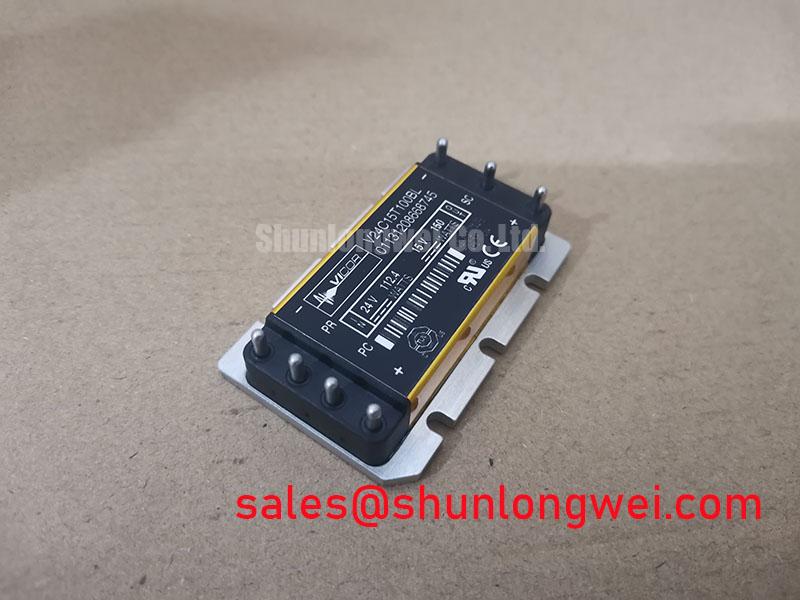
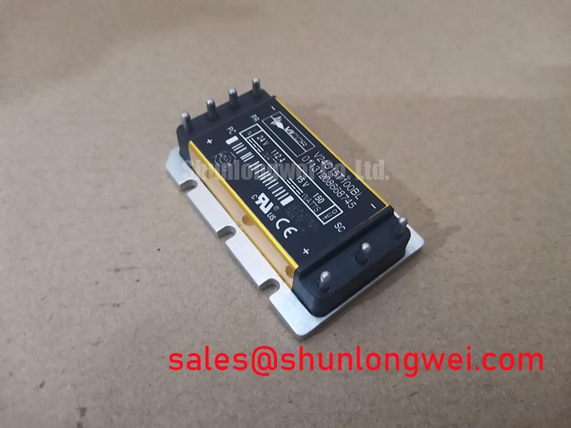
Measure the converter input and output terminals with the equipment isolated, then compare the observed cold-state resistance and terminal condition with a known-good unit before reconnecting the industrial inverter welder or medium-frequency induction heating supply. The supplied hardware data identifies V24C15T100BL as a Vicor DC-DC converter, while numerical operating-voltage and current ratings are not provided in the available product specification set. Do not infer a bus-voltage limit from the model name.
For a replacement assessment, record the original converter’s input rail, regulated output rail, polarity, control connections, and mechanical interface. The system integrator should verify each value against the equipment schematic and the original Vicor documentation. A converter that fits the same mounting position may still be unsuitable if its input range, output regulation behavior, protection response, or control timing differs from the installed unit.
DC-bus headroom is a system-level design consideration. Switching transients, rectifier commutation, regenerative energy, wiring inductance, and the operating profile of the welding or induction-heating stage can move the applied voltage away from its nominal value. Designers should measure the highest observed bus voltage at the converter terminals during startup, shutdown, load transition, and fault recovery, then compare that waveform with the confirmed V24C15T100BL operating limits. The final margin must be established by system testing rather than by a generic derating percentage.
Altitude-related radiation effects and single-event burnout require source-specific reliability data. No FIT rate, neutron-flux limit, altitude derating curve, or SEB withstand value is available in the supplied parameters, so these values must not be assigned to this product. At installations above 2000 m, treat reduced cooling, altered insulation conditions, and transient exposure as design considerations and validate the complete assembly using the applicable equipment standards and manufacturer data.
Keep the high-current DC path short and physically controlled. Separate sensitive control wiring from rectifier and switching-node conductors, and verify creepage, clearance, protective earthing, and enclosure spacing against the actual voltage category of the equipment. For broader power-stage review, engineers can consult IGBT Design & Integration as a practical reference for layout, switching stress, and thermal integration principles.
Benchtop Waveform Tuning: Gate Loop Layout in Surrounding Switching Stages
Probe the converter control and power-return paths at the connector pins while the unit remains disconnected from the main switching stage, checking for unexpected common-mode movement, ringing, or control pulses during enable and disable transitions. The supplied data does not define gate-drive terminals, Kelvin-emitter terminals, auxiliary returns, dead-time, or gate-loop requirements for V24C15T100BL; those features must not be assumed from the product category.
Where the surrounding inverter uses IGBT or MOSFET switching devices, separating the high-current return from the quiet control return is a general Design Consideration. Route the power return according to the switching-current path and give the control reference its own deliberately defined return path. The objective is to reduce mutual coupling and prevent a voltage developed by load current from being interpreted as a control signal. The exact routing, layer arrangement, and termination remain determined by the converter and system schematics.
Use a differential probe or an appropriately rated isolated measurement method when checking switching-node behavior. Confirm that the probe connection does not create an unintended current loop. During bench testing, compare enable timing, output settling, and fault recovery against the known-good assembly. If the waveform changes when the probe ground is moved, investigate measurement-induced coupling before changing component values.
Bootstrap capacitors, high-frequency charging paths, and diode recovery belong to the surrounding switching topology rather than to the confirmed physical description of this converter. Designers should verify capacitor voltage rating, charging-current capability, diode reverse-recovery behavior, and local decoupling from the original circuit documentation. For topology context, a matrix converter nine-switch bidirectional topology and a modular multilevel converter in VSC-HVDC systems use different switching arrangements and cannot be treated as interchangeable reference circuits.
When comparing possible alternatives, the VI-2W4-CV should be evaluated as a separate product rather than presumed to be a drop-in replacement. Check electrical ratings, pin assignment, package dimensions, control behavior, thermal path, and compliance requirements before considering any substitution.
Field Diagnostics & Commissioning: Overcurrent Protection in V24C15T100BL Applications
Capture the converter input current, output voltage, enable state, and fault indication during a controlled startup, then compare the timing with the equipment’s service documentation. The available hardware parameters do not specify short-circuit safe operating area, a type-I or type-II short-circuit response, a sub-10-microsecond protection threshold, or a two-stage soft turn-off function for V24C15T100BL. These characteristics must therefore be verified from the applicable Vicor documentation and the complete system schematic.
For an industrial inverter welder, inspect the input rectifier, DC-link capacitors, switching bridge, output rectifier, and load cable before condemning the converter. A repeated protection event may involve excessive inrush, a downstream short, unstable feedback, incorrect enable sequencing, inadequate cooling, or an external switching transient. Treat the symptom as a test prompt rather than a single-cause diagnosis.
During commissioning, use current limiting appropriate to the equipment and introduce the load in controlled stages. Monitor whether the output collapses at startup, only during load transitions, or after thermal rise. Verify the signal path from the controller to the converter and check whether fault recovery is being commanded repeatedly. If a two-stage turn-off circuit exists elsewhere in the system, its response must be tested with the actual parasitic inductance and switching conditions present in the installed assembly.
Long motor or work-head cables can behave as transmission lines and may produce reflected-wave overvoltage at the load or switching terminals. Filtering, damping, cable routing, and termination should be selected from measured waveforms and system requirements. The converter’s product description alone does not establish a permitted cable length, filter value, or overshoot limit.
Field Alert: Disconnect power and verify the DC link has discharged before removing any converter connector or handling control wiring.
V24C15T100BL Circuit Protection & Reliability: Checking Insulation Barrier Integrity
Check insulation resistance, protective-earth continuity, connector condition, and control-to-power isolation with the converter removed from sensitive circuitry and with the test method approved for the equipment. The supplied specifications do not state a reinforced-isolation voltage, a greater-than-5-kV barrier rating, a common-mode transient immunity value, or an EMC certification for V24C15T100BL. Do not assign those values to the product or describe the individual converter as independently certified for the complete machine.
Isolation verification must match the converter’s actual construction, test points, pollution environment, working-voltage category, and safety standard. A production hipot or insulation-resistance test should be applied only at the level and duration permitted by the manufacturer’s documentation. Excessive or incorrectly connected test voltage can damage control circuitry and produce a misleading service result.
Spurious enable pulses can result from common-mode displacement, inadequate return definition, connector contamination, probe coupling, or control-board timing faults. Observe the control signal at both the source and converter terminals, then compare the two waveforms during switching transitions. If the signals differ, inspect the interconnect and reference path before changing the controller threshold.
For an induction-heating power supply, evaluate rectifier conduction angle, line-current distortion, and harmonic filtering as system-level functions. The correct filter and control strategy depend on the supply architecture, power factor requirements, source impedance, and measured current waveform. The same principle applies to inverter welders: verify the complete power path under the actual load rather than treating the converter package as proof of system compliance.
Thermal inspection should include the mounting surface, airflow path, connector temperature, adjacent switching devices, and the converter’s measured case temperature under representative duty. The supplied data gives no guaranteed thermal-resistance value, maximum case temperature, lifetime figure, or field-failure rate. Reliability decisions should therefore use documented manufacturer limits and measured equipment conditions, with protection thresholds validated during commissioning.