

Content last revised on September 21, 2026
V300B28H150BL Circuit Protection & Reliability: Calibrating Isolated DC to DC Power Supply Sizing for High Energy Switching Systems
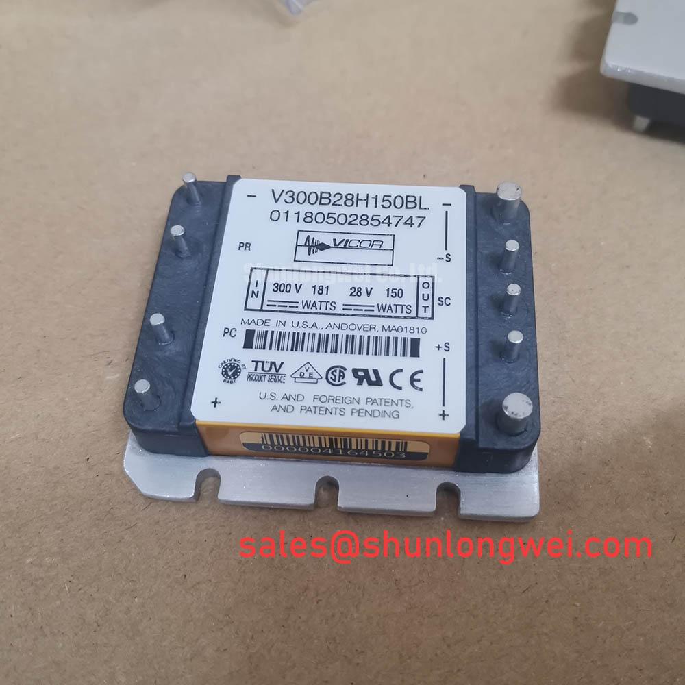
Before fitting the V300B28H150BL, isolate the equipment, inspect its connector interface and housing for heat discoloration or contamination, then compare the unit marking with the original service record. The available official structured specification identifies this Vicor DC to DC converter at 36.0 A, with a listed enclosure description of Maxi / Mini / Micro Module and a Standard Industrial Rating voltage classification. The system integrator should verify the required input range, output voltage, isolation rating, pin assignment, remote control logic, and thermal limits from the original equipment documentation before replacement or redesign work.
| Parameter | Declared Value | Classification |
|---|---|---|
| Part number | V300B28H150BL | Official identification |
| Manufacturer | Vicor | Official identification |
| Current rating | 36.0 A | Official Specification |
| Voltage classification | Standard Industrial Rating | Official Specification |
| Enclosure description | Maxi / Mini / Micro Module | Official structured listing |
| Product class | DC to DC Converter | Product classification |
In commercial string inverters and micro grid energy storage equipment, a DC to DC converter can serve as part of the control power architecture, auxiliary supply network, or isolated supply arrangement. The 36.0 A rating is an Official Specification, but it does not independently establish the converter’s permissible power level in a particular installation. Actual loading depends on the verified input condition, output requirement, ambient temperature, airflow, wiring resistance, startup demand, and the electrical behavior of all connected loads.
For a repair assessment, begin by mapping the converter connection points against the original schematic. Identify whether its output feeds logic controls, relay coils, communication interfaces, sensing circuits, or isolated gate drive circuitry. Check for loose contacts, overheated mating surfaces, residue on insulation, and signs of moisture exposure around the converter compartment. A voltage drop observed at the downstream load can arise from cable resistance, terminal condition, upstream supply behavior, excessive load demand, or converter regulation characteristics. It should be measured through the known good signal path rather than assigned to one cause without evidence.
Isolation barriers and common mode transient immunity are system properties that require confirmation from the relevant Vicor documentation and the completed assembly. No verified official value is provided here for reinforced isolation exceeding 5 kV or for common mode transient immunity exceeding 100 kV per microsecond. Design Consideration: Where the converter supplies circuitry referenced to a fast switching power stage, engineers should maintain appropriate separation between high energy switching conductors and low level control wiring, then validate noise behavior during real switching tests. This helps reveal unexpected control disturbances without treating unverified immunity figures as product ratings.
Protection coordination also needs to be established at the equipment level. Input fusing, disconnect arrangements, transient control components, and downstream overcurrent protection must be selected against the host equipment’s documented electrical limits. A converter replacement should preserve the original interface arrangement and should not be used to assume that external protection components can be omitted.
⚠️ Maintenance Note: Monitor connector and cable contact temperature during normal load operation, and keep the cabinet air path clear of dust that can restrict heat removal.
V300B28H150BL Circuit Protection & Reliability: Calibrating PCB Symmetry Considerations for Dual IGBT Systems
The V300B28H150BL is identified as a Vicor DC to DC converter, not as a dual IGBT module. It therefore cannot be assigned IGBT parameters such as collector emitter saturation voltage, short circuit withstand capability, freewheeling diode reverse recovery performance, or Kelvin emitter terminals without verified manufacturer documentation. Its relevance in a switching assembly is as a power conversion element whose wiring, return path, and load behavior can influence the stability of associated control circuits.
Design Consideration: In a bridge using dual IGBTs or other fast switching devices, separate the low level control return path from the main high current emitter or source return where the original equipment topology requires it. Shared impedance in a common return can translate switching current into an unwanted gate reference disturbance. The practical objective is to minimize parasitic loop coupling where it could affect turn off behavior, while the system engineer verifies switching waveforms and peak margins under the actual DC link and load conditions.
When a converter output feeds a gate driver or a local control card, inspect the distribution wiring for routing changes introduced during maintenance. Long parallel runs alongside high current conductors, compromised cable shielding, oxidized terminal interfaces, and altered return routing can all affect the observed waveform. Use an oscilloscope and the known good measurement method specified for the equipment to compare command signals, local supply stability, and switching node activity. Avoid probing arrangements that unintentionally add a large loop area and distort the result.
Freewheeling diode recovery behavior, snubber selection, and radiated emissions belong to the inverter power stage design rather than to an unverified attribute of this converter. Engineers evaluating repairs to an integrated converter and IGBT assembly can review the function of an associated 7MBR35UB120 device in the relevant equipment topology, subject to its own datasheet, interface, and operating requirements. This is a compatibility review, not a direct replacement recommendation.
For control and protection signal verification, a current measurement path should be assessed as a complete chain including shunt or sensor placement, amplifier behavior, reference routing, and controller interpretation. The technical material from ADI High Precision Current Sense Amplifiers is a useful external reference for examining current sensing architectures and measurement limitations.
V300B28H150BL Operational Boundaries: Evaluating DC Bus Operating Voltage Headroom Derating Limits
The part number and supplied structured data do not provide an official input voltage range, DC bus rating, altitude rating, neutron induced failure rate, or single event burnout performance for the V300B28H150BL. It would therefore be inappropriate to calculate a failure in time value, prescribe a DC bus derating percentage, or state a safe altitude boundary for this specific converter.
Design Consideration: At elevated installation sites or in systems exposed to high energy switching transients, the equipment team should assess the complete electrical and environmental design using the converter manufacturer’s verified ratings, the inverter manufacturer’s system requirements, and applicable installation standards. This assessment should consider insulation coordination, enclosure contamination level, condensation risk, input transient exposure, conductor spacing, and the measured peak voltage across each relevant circuit. The final operating margin is determined by system testing rather than a universal value.
For field troubleshooting, record the DC bus condition during startup, steady state, load changes, and protective shutdown. Then compare these records against the original system documentation. If auxiliary power faults coincide with bus switching activity, inspect the physical location of converter wiring and control harnesses before changing component values. An intermittent symptom may indicate coupling, grounding, input instability, a load side fault, or a connection issue, so the investigation should retain measured evidence from each path.
Repair teams dealing with resonant or half bridge energy conversion equipment can use Resonant Topologies in Home Appliances as a practical reference for examining switching topology behavior. The reference supports method selection for measurements; it does not establish product specific voltage, transient, or reliability ratings for the V300B28H150BL.
Where a service evaluation considers another module, electrical compatibility must be verified against the original circuit diagram, mechanical interface, thermal environment, protection coordination, and documentation. The linked 5SNG015045P0301 can be reviewed as a separate component during a documented hardware evaluation, but it should not be treated as an automatic replacement for a Vicor DC to DC converter.
V300B28H150BL Thermal Electrical Optimization: Derating Guidelines and Mismatched Parameter Practical Tuning
Thermal maintenance starts with the surrounding assembly. Verify that the converter is seated as specified by the host equipment, that its cooling surfaces and adjacent airflow passages are clean, and that nearby harnesses do not obstruct ventilation. Inspect thermal interface materials only where the original mechanical construction uses them, and replace aged material according to the equipment manufacturer’s service procedure. The available structured information does not state a case temperature limit, thermal resistance, mounting torque, or approved heatsink arrangement for the V300B28H150BL.
The positive temperature coefficient of IGBT collector emitter saturation voltage can assist static current sharing among matched parallel IGBTs under suitable operating conditions. This is an IGBT power stage behavior, not a declared characteristic of the V300B28H150BL. Dynamic current balance remains sensitive to gate loop symmetry, device matching, driver timing, bus layout, and operating conditions. When auxiliary converter power supports the driver system, technicians should verify that supply behavior remains stable during the switching events that matter to the host design.
Do not transfer IGBT short circuit protection concepts directly to this DC to DC converter. Desaturation sensing, soft turn off action, short circuit safe operating area, surge current limits, thyristor gate trigger parameters, and pulse train triggering must be taken from the exact semiconductor and driver documentation used in the assembly. Where a protection event has occurred, inspect the converter input and output connections, control enable path, attached loads, and cooling condition before deciding whether the converter is implicated.
For ongoing preventive maintenance, maintain a log of cabinet temperature, fan condition, heat sink cleanliness, terminal tightness checks, moisture observations, and any protective events reported by the controller. In commercial string inverter and micro grid energy storage installations, this disciplined record helps distinguish gradual thermal or connection related deterioration from control side disturbances, while preserving the verified electrical boundaries of the original equipment.