Content last revised on October 17, 2026
Assembly Integrity & Layout Architecture: Inspecting the VI-J60-IZ Brick Module
Disconnect the equipment supply, verify that stored energy has discharged, and compare the converter terminal connections with the equipment schematic before removing the VI-J60-IZ. During a repair, record the input polarity, output connections, mounting arrangement, and surrounding components so the replacement assessment includes the actual installation.
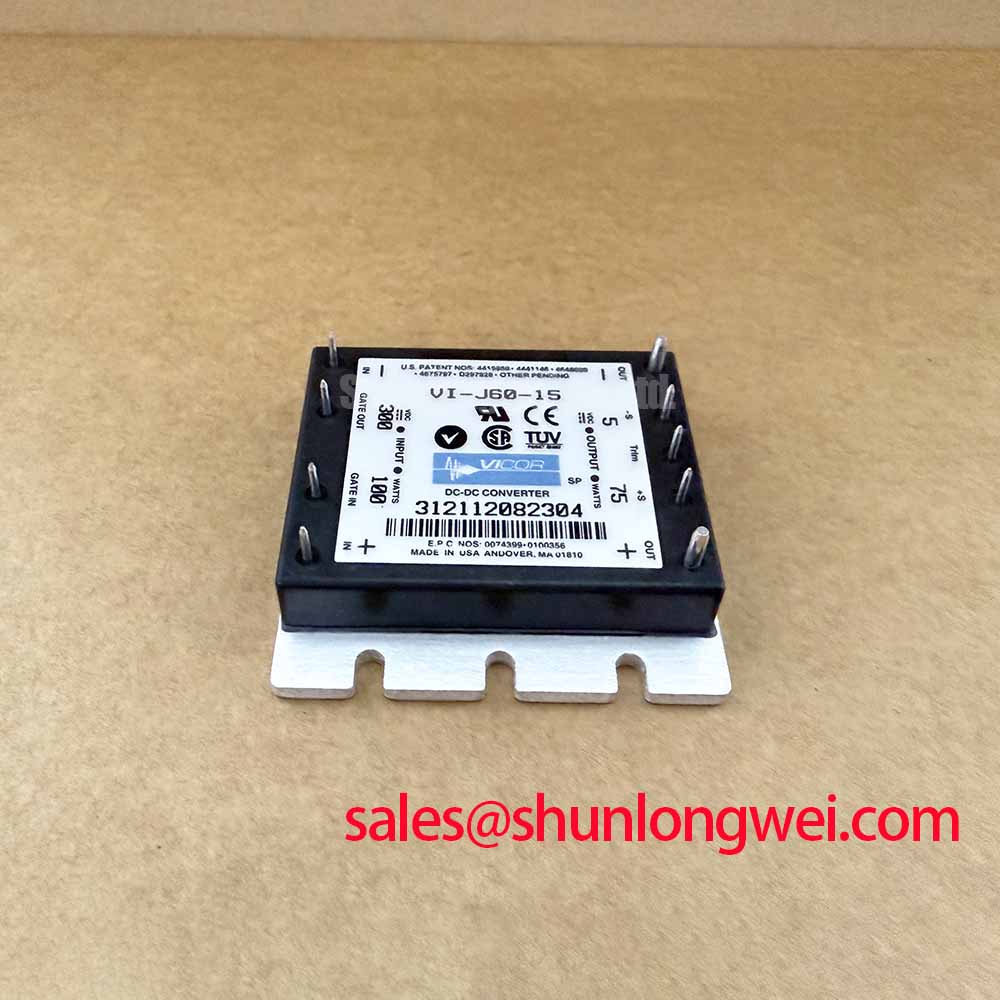
The Vicor VI-J60-IZ belongs to the Power Supply / DC-DC Converter category and uses a brick module package. Its role in an assembly is power conversion; gate drive adjustment, braking energy absorption, and motor output filtering belong to the surrounding circuitry. For purchasing comparison, record the exact input range, output voltage, output current, isolation specification, and mechanical drawing from the applicable Vicor datasheet rather than treating a package description as an electrical rating.
Inspect the converter terminals, mounting surfaces, and adjacent circuit board for contamination, damaged connections, displaced hardware, and evidence of uneven mechanical loading. Compare terminal positions and clearances with the assembly drawing before applying power. A matching brick outline alone does not establish electrical or mechanical compatibility.
Design Consideration: Surface contamination can create leakage paths around terminals and across the supporting board. Cleaning should follow the assembly manufacturer’s process, including material compatibility and drying requirements. Inspect the surrounding insulation barriers as well as the converter, because leakage measured within an assembled power supply can include paths through filters, protection components, and external wiring.
An insulation assessment should distinguish input, output, and baseplate connections according to the manufacturer’s prescribed test arrangement. The test voltage, terminal grouping, duration, and acceptance criteria must come from that procedure. An arbitrary insulation tester setting can stress connected circuitry and produce a reading that does not represent the converter alone. External inspection also cannot establish the condition or composition of an undocumented internal ceramic substrate.
For a sourcing comparison, the PAF600F24-28T can be recorded as a separate power conversion candidate for specification review. Compare its input range, output characteristics, isolation arrangement, mounting dimensions, and connection layout individually; its inclusion in a comparison does not establish interchangeability with the VI-J60-IZ.
Benchtop Waveform Tuning: Evaluating DC-Bus Layout Around the VI-J60-IZ
Measure the waveform directly across the converter input terminals while recording startup, load changes, and shutdown. Use a probing arrangement suitable for the circuit potential and bandwidth, with a short measurement loop. Compare the terminal waveform with the upstream supply waveform to distinguish source disturbances from voltage developed across the interconnecting wiring.
Design Consideration: Parasitic inductance in a supply path can produce transient voltage when current changes rapidly. Short, closely coupled supply and return paths can reduce that contribution, but the appropriate geometry depends on insulation requirements, connector placement, and the equipment’s current paths. A laminated busbar belongs to the system layout assessment; it is not an established feature or requirement of this converter.
Input filtering should be evaluated together with source impedance and converter behavior. Adding capacitance or damping without examining startup and load response can change inrush, resonance, or protection operation. Record the observed behavior before changing the network, then assess each change against the applicable electrical limits and the equipment’s operating conditions.
Practical tip: Keep the converter supply and return paths closely coupled where insulation requirements permit, then verify terminal transients under representative operating conditions.
Protection coordination requires the actual fuse characteristics, available fault current, wiring capability, and documented converter protection behavior. A semiconductor fuse specification does not establish coordination by itself. In the system power tree, the PH150A280-24 can be assessed as a separate conversion stage, with its interface checked independently rather than assigned an assumed rectifier or front-end role.
VI-J60-IZ Operational Boundaries: Evaluating Dynamic Braking Chopper Operation Limits
Trace the braking energy path on the equipment schematic before deciding whether a converter disturbance originates in the braking circuit. The braking switch, resistor, DC-link capacitance, and control thresholds determine how regenerated energy is handled. The VI-J60-IZ should be assessed at its own input and output interfaces rather than assigned braking switch ratings.
For compatibility evaluation in a heavy-duty variable frequency AC motor drive, engineers should first identify the converter’s proposed auxiliary supply role and the voltage presented to its input. Record whether that source changes during acceleration, deceleration, emergency stopping, or supply interruption. A converter connected through an intermediate supply stage experiences the behavior of that stage, not necessarily the raw DC-link waveform.
Design Consideration: If an auxiliary rail drops during braking, compare the timing of its input disturbance, output response, and downstream load demand. Several mechanisms can produce similar symptoms, including source protection, connection resistance, or a changing auxiliary load. Synchronized measurements provide a stronger basis for diagnosis than assigning a single cause from the equipment alarm alone.
For the separate inverter or braking semiconductor assessment, The Ultimate IGBT Knowledge Base provides background on switching behavior. Component acceptance limits must still come from the relevant manufacturer documentation. Gate loop inductance and Miller coupling concern those switching stages; their test results should not be presented as specifications of the Vicor converter.
VI-J60-IZ Thermal-Electrical Optimization: Separating Converter Heating from Common-Mode Disturbances
Record the converter mounting surface temperature alongside input voltage, output loading, and enclosure conditions when investigating heating. Compare measurements at consistent locations and operating states. Changes in airflow, contact condition, nearby heat sources, and electrical loading can affect the result, so a temperature observation needs its installation context.
Design Consideration: Maintain the intended thermal contact and mounting arrangement without imposing board strain or terminal loading. Interface materials, fastening procedures, and allowable temperatures should follow the applicable assembly documentation. A brick package description does not establish a mounting torque, thermal resistance, or permitted case temperature.
Common-mode disturbances require a separate measurement path. Examine cable routing, chassis connections, and the relationship between converter return and equipment reference points. In a motor inverter, reflected waves and bearing currents involve the inverter output network, motor cable, and motor construction. Output filter selection therefore belongs to that system assessment rather than the converter’s product rating.
The Clarke Transformation (Alpha-Beta Coordinate Transformation) in Motor Drives explains a coordinate transformation used in motor control analysis; it does not establish insulation, thermal, or transient limits for the VI-J60-IZ. When checking interference with an auxiliary supply, correlate the converter input and output disturbances with switching activity, then evaluate routing or filtering changes through repeatable measurements at the affected interface.