Content last revised on September 15, 2026
W2664NC400 Thermal Electrical Optimization: Fuse Total Clearing I2t versus Device Melt Practical Tuning
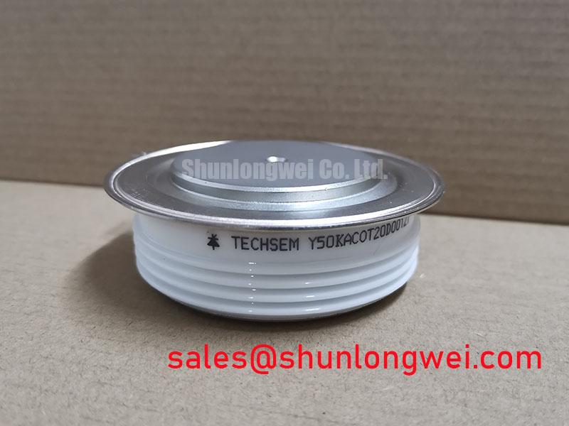
Before installation, isolate the rectifier assembly, confirm that stored energy has been discharged, and verify the nameplate boundary of 4000 V VRRM and 2664 A IFAV against the original equipment documentation. The Westcode W2664NC400 is a standard recovery rectifier supplied in an O CEDB N2 capsule presspack configuration. Its pressure contact arrangement has no lead terminals, so the electrical and thermal result depends on clean mating surfaces, correct stack hardware, controlled clamping force, and the condition of the surrounding cooling system.
The official ratings identify this device as a high current rectifier for low frequency power conversion. Its 4000 V repetitive peak reverse voltage is the official datasheet specification, while 2664 A average forward current is specified under double side cooling conditions. The official 29.2 kA non repetitive peak forward surge current indicates short duration surge capability, but it is not a continuous current rating or a substitute for coordinated fault protection.
| Official specification | Rated value | Integration relevance |
|---|---|---|
| Repetitive peak reverse voltage, VRRM | 4000 V | Reverse voltage boundary for the rectifier position |
| Average forward current, IFAV | 2664 A | Specified with double side cooling |
| Non repetitive forward surge current, IFSM | 29.2 kA | Short duration fault and inrush coordination reference |
| Package configuration | Capsule presspack, O CEDB N2 | Pressure contact mounting system required |
| Diode type | Standard recovery rectifier | Appropriate for low frequency rectification assessment |
For a presspack diode in a high energy rectifier, fuse coordination begins with the actual fault path, not with a nominal current label. Trace the AC source, transformer secondary, busbar path, diode position, DC link, and any parallel branches. The 29.2 kA IFSM rating is an official non repetitive peak forward surge specification and provides one boundary for reviewing prospective fault current. It does not publish a fuse total clearing I2t value, diode melting I2t value, or a permitted coordination curve. Those values must therefore be obtained from the selected semiconductor fuse documentation and the applicable Westcode technical documentation before a protection decision is made.
As a Design Consideration, compare the fuse pre arcing behavior and total clearing behavior at the calculated prospective fault current with the complete rectifier assembly withstand capability. The practical objective is for the protective device to interrupt a dead short before the diode, busbars, clamps, and connected transformer conductors experience destructive thermal or electrodynamic stress. A fuse selected only by its continuous current marking can be unsuitable where transformer impedance, capacitor discharge, or parallel rectifier paths alter the first fault half cycle.
In medium frequency induction melting and hardening furnace power supplies, the front end rectifier is often evaluated as part of a larger conversion chain. The W2664NC400 is a standard recovery diode, so the system integrator should verify that the line frequency, commutation conditions, transformer arrangement, and intended rectifier topology align with that recovery class. It should not be assigned an assumed role in an inverter leg or a gate controlled bridge. Where a maintenance engineer is comparing equipment documents, the linked SKN320-04 can serve as a neutral reference point for reviewing related rectifier positions, but electrical and mechanical interchangeability requires a full drawing and ratings review.
Pressure contact assemblies require more than a visual inspection. Remove oxidation, foreign material, dried compound residue, and raised marks from contact faces according to the equipment service method. Confirm that the clamp, insulators, busbars, and heatsink faces are flat and correctly seated. The manufacturer supplied mechanical drawing and the original clamp specification should govern clamping force and tightening sequence; no mounting torque can be inferred from the W2664NC400 electrical ratings alone.
⚠️ Maintenance Note: Monitor contact temperature rise during normal production loading and inspect cooling air paths, interface condition, and clamp hardware whenever the scheduled maintenance plan identifies abnormal heating.
Field Diagnostics & Commissioning: Gate Trigger Current Dynamics in W2664NC400 Topologies
The W2664NC400 is a diode and has no gate terminal, gate trigger current, holding current, or firing pulse requirement. Gate pulse rise time, back porch current, multi pulse firing, and thyristor gate hotspot analysis are therefore not applicable to the device itself. Treating this capsule diode as a gate controlled semiconductor during commissioning can lead to an incorrect test setup and a misleading fault record.
Where the same converter contains thyristors or actively driven switching devices, their gate drive checks must remain separate from W2664NC400 validation. A useful commissioning record identifies each pressure contact diode by its physical rectifier location, verifies polarity from the installed circuit drawing, and captures the conditions under which voltage appears across the device. With power removed and all energy storage confirmed safe, technicians can compare the diode path against a known good parallel position using the approved low energy test method. A divergent result may indicate a device, contact, busbar, or measurement path issue; it should be investigated with circuit isolation rather than attributed to one cause automatically.
Standard recovery behavior also matters when interpreting waveforms. In a low frequency rectifier, reverse recovery and transformer leakage can influence commutation transients, while the actual outcome depends on source impedance, load current, wiring geometry, snubber network, and measurement bandwidth. The system engineer should verify voltage and current traces at the original test points, using appropriately rated differential measurement equipment, before modifying a protective network.
Some furnace power supplies use controlled rectification upstream of diode sections. In that arrangement, review firing synchronization, line phase reference, commutation overlap, and harmonic behavior as characteristics of the controlled system, not as W2664NC400 specifications. Current sharing among parallel paths also requires evidence from the complete assembly. Similar ratings alone do not establish a replacement relationship; for comparison work, 2DI75M-120 is a separate device reference that should be assessed only against the original circuit requirements.
The proximity of high current conductors can change observed AC resistance and magnetic coupling. The physical mechanism is described in this technical reference on the proximity effect. As a Design Consideration, keep diagnostic probes and temporary sense conductors routed consistently with the approved test arrangement so that the measurement itself does not introduce an avoidable pickup path.
Field Diagnostics & Commissioning: Ensuring Uniform Heatsink Contact Pressure in W2664NC400 Topologies
The official 2664 A IFAV rating is stated under double side cooling conditions. That condition is central to integration because a capsule presspack transfers heat through both pressure contact faces into the cooling structure. The supplied parameter set does not state a junction to case thermal resistance, maximum junction temperature, clamping force, permitted tilt, heatsink flatness, interface material thickness, or tightening torque. These must not be invented during maintenance planning; obtain them from the applicable manufacturer documentation and the installed equipment drawing.
Begin the mechanical inspection with the stack unloaded and isolated. Check whether both heatsink faces are free from scoring, embedded debris, corrosion products, and local dents. Inspect spring stacks, load spreaders, alignment features, and insulation parts for deformation or incorrect assembly order. A presspack can appear correctly located while carrying uneven contact force, particularly if a busbar is pulling the stack sideways or a clamp has been tightened unevenly.
As an Engineering Recommendation, use the original fixture procedure to apply pressure progressively and symmetrically. Confirm that the diode sits squarely in the designated pocket and that no conductive debris bridges adjacent live metalwork. Where thermal interface material is part of the approved assembly, apply only the specified material and method from the equipment documentation. Excess material, unapproved shims, or uncontrolled resurfacing can change the thermal path and electrical spacing.
During a controlled return to service, compare cooling inlet and outlet condition, airflow or liquid flow indication where fitted, and temperature trends across equivalent rectifier positions. A local increase in contact temperature may arise from uneven pressure, blocked cooling, altered current sharing, deteriorated interface material, or a changed load profile. The appropriate response is to inspect and measure the entire path rather than to assume a single thermal resistance value.
Moisture control also deserves routine attention. Condensation on busbars, insulating supports, or cooling manifolds can introduce surface leakage and corrosion risk. Keep enclosure seals, drain paths, cabinet heaters, and ventilation serviceable according to the site maintenance schedule. For materials context, the dielectric and chemical characteristics of polytetrafluoroethylene are relevant when reviewing verified insulation materials in high voltage assemblies, although no PTFE construction should be assumed for this diode.
Transient Dynamics & Electrical Design: AC Input Transient Overvoltage Clamping on W2664NC400
The 4000 V VRRM rating is the official repetitive peak reverse voltage limit for W2664NC400. It is not a published statement of surge immunity for a complete furnace cabinet, and it does not establish MOV selection, RC snubber values, insulation coordination, EMC compliance, or protection against every input transient. These outcomes are determined by the source, transformer, switching sequence, line impedance, installation wiring, and protective components around the diode.
For an AC input protection review, first obtain captured waveform data from the equipment under representative operating and disturbance conditions. Check the installation drawing for surge arresters, MOVs, RC networks, fuses, contactors, transformer taps, and any existing suppression assemblies. The system designer should then verify peak reverse voltage margins at the diode position during switching and fault related tests, considering the measured source behavior and the approved rating of every protective element. RC networks should be assessed as complete loops, because long connections can reduce their effectiveness during fast events.
IEC 61000-4-5 is commonly used at equipment level for surge immunity evaluation. It does not certify an individual diode as compliant with an installed power system. When reviewing a furnace rectifier cabinet, engineers should use the system test plan and governing product standards to determine whether surge testing is required and how the AC supply, protective earth, control wiring, and connected auxiliaries are configured.
Long motor cables, inverter switching edges, bidirectional DC DC stages, and gate drive dead time are not inherent operating functions of this standard recovery diode. They may exist elsewhere in a facility power system and should be evaluated at their own semiconductor locations. For wider context on switching loss and industrial drive technology, see Unlocking Efficiency in Industrial Drives. Keep that discussion separate from the W2664NC400 rectifier role so that device selection, fault records, and maintenance actions remain technically traceable.
Before returning a repaired rectifier stack to operation, verify polarity, clamp alignment, fuse installation, protective earth continuity, cooling readiness, and the absence of tools or loose hardware. Controlled energization with the original commissioning procedure provides a more reliable check than assuming that a satisfactory static diode test confirms performance under operating current and voltage.