

Content last revised on October 3, 2026
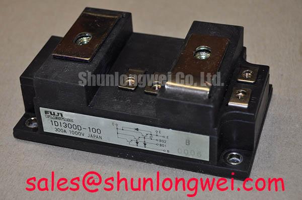
Fuji Electric 1DI300D-100 Product Data
| Specification | Official Product Data |
|---|---|
| Manufacturer | Fuji Electric |
| Model | 1DI300D-100 |
| Product category | Power Transistor and Darlington Module |
| Package | Power Transistor Module |
| Rated current | 300.0 A |
| Voltage information | Standard Industrial Rating; numerical rating not provided here |
Benchtop Waveform Tuning and Voltage Boundary Checks
Measure the unpowered terminal-to-terminal resistance and diode response of the 1DI300D-100 before connecting it to a variable frequency AC motor drive, then compare the cold-state readings with a known-good unit from the same equipment family. A diode-test reading can help confirm expected polarity paths, but it cannot establish switching performance, insulation condition, or short-circuit withstand capability by itself.
The listed 300.0 A rating is an official product parameter, not a complete system operating limit. The DC-link voltage, switching frequency, duty cycle, cooling arrangement, overload profile, and commutation layout must be checked against the original Fuji Electric documentation and the drive manufacturer’s limits. The supplied product data identifies the voltage as a standard industrial rating without providing a numerical voltage value here; do not infer a voltage rating from the model number.
Cosmic-ray, terrestrial-neutron, altitude, and Single Event Burnout assessments require device-specific reliability data and the actual DC-link operating history. Without a qualified source, treat them as design considerations rather than calculated FIT values. During commissioning, capture collector-emitter voltage and current with suitably rated probes, inspect turn-off overshoot, and verify that the measured peak remains within the confirmed device and system boundaries.
💡 Bench Tip: Use ESD protection and record cold-state baseline measurements before applying base drive or DC-link power.
Protection Coordination for Pulsed Power Loss
Check the base-emitter and power-terminal waveforms during a controlled low-energy test, while monitoring case temperature and current rise, when investigating abnormal dissipation in a 1DI300D-100 stage. A transient thermal model can support engineering calculations, but its RC values must come from the applicable datasheet or a validated thermal characterization rather than a generic module assumption.
Protection coordination should combine current sensing, base-drive supervision, DC-link fault handling, and an appropriately selected semiconductor fuse where the system topology requires one. Fuse let-through I²t, wiring inductance, base-drive delay, and the module’s documented fault limits must be evaluated together. Collector-emitter voltage monitoring may be considered where supported by the drive architecture, but detection time, turn-off behavior, and fault energy remain system-dependent. Do not assign a sub-microsecond or microsecond protection limit to this model without an authoritative source.
In regenerative braking, confirm that the braking chopper and resistor can absorb the expected kinetic and electrical energy without forcing the DC link beyond its verified limit. The module’s 300.0 A current rating does not by itself define braking-resistor energy capacity. Engineers comparing devices within a drive platform may review 2MBI200J-120 as a separate product for objective electrical and mechanical comparison, not as an automatic substitute.
Field Diagnostics for Drive-Induced Cross-Conduction
Probe both complementary drive signals and the switching-node voltage at the driver and module terminals when a drive shows unexplained shoot-through, irregular current spikes, or unstable turn-off behavior. Compare dead-time behavior under the actual DC-link and load conditions, because probe ground inductance, common-emitter wiring, driver delay, and parasitic capacitance can distort a bench waveform.
Turn-off base bias and base-drive circuitry should be selected according to the module documentation, isolation system, and power-sequencing design. The values must be determined by the system engineer; they should not be assigned to the 1DI300D-100 without confirmed base-drive specifications. Keep the base-drive loop compact, separate power and signal return paths where practical, and verify the base-emitter voltage directly during the highest dv/dt operating condition.
The related QM200HA-HK can be reviewed as a neutral reference when comparing power modules within the same power-conversion system. It should not be treated as a guaranteed complementary match without checking current, voltage, terminal arrangement, thermal interface, and control requirements.
Assembly Integrity and Fault-Clearing Layout
Inspect mounting flatness, terminal torque records, thermal-interface coverage, and power-loop routing when a newly installed module trips protection or exhibits excessive switching overshoot. Clean the mounting surfaces, apply the thermal interface material evenly according to the assembly specification, and verify that the heatsink contact is uniform; the exact compound thickness and fastener torque must come from the mechanical documentation for the assembly.
Collector-emitter voltage monitoring can be evaluated for fault clearing, but the applicable detection interval, turn-off profile, and safe-operating-area limits must be taken from the selected driver and the confirmed Fuji Electric data. The protection network should limit fault energy while avoiding excessive turn-off voltage caused by stray inductance. Validate the result with isolated voltage and current probes during controlled fault testing rather than relying on a nominal timing label.