Content last revised on October 16, 2026
1DI400D-100 Operational Boundaries: Evaluating Short-Circuit Protection Limits
Isolate the DC link, verify that stored energy has discharged, and disconnect parallel circuit paths before checking collector-to-emitter resistance on a Fuji Electric 1DI400D-100. Compare readings with the equipment schematic and service records; an in-circuit resistance measurement alone cannot establish the module’s condition. This Power Transistor / Darlington Module has a listed rated-current specification of 400.0 A. Confirm the blocking voltage and current-rating conditions in the manufacturer’s datasheet.
The Darlington classification matters when inspecting the driver: this is a base-driven bipolar device, so IGBT gate-charge, Miller-clamp, and Kelvin-emitter assumptions cannot define its connections or protection requirements. Establish the actual terminal arrangement and base-drive circuit before evaluating a replacement.
Compare the semiconductor fuse’s total clearing I²t at the installation’s prospective fault current with the documented withstand limits of the protected circuit. Design Consideration: fuse coordination must account for DC-link capacitor discharge, supply contribution, interruption voltage, and fault-loop impedance. A current rating alone cannot establish whether a fuse will clear before destructive semiconductor stress develops.
Separate fuse interruption from transistor protection. The fuse addresses fault energy within its operating characteristics; the driver’s fault response addresses the transistor’s electrical stress before interruption completes. Review current detection, base-drive removal, and the resulting collector-voltage transient together. Neither a fuse label nor a nominal interruption time establishes containment of a failed module.
During fault investigation, inspect the capacitor connections, fuse holders, and conductor spacing for evidence of arcing or displaced hardware. Use the equipment’s insulation requirements to assess clearance. Treat any diode surge-current rating and the transistor’s safe operating area as distinct limits, including their temperature and pulse conditions. The Field Engineer’s Handbook provides related troubleshooting context for organizing these checks.
Assembly Integrity & Layout Architecture: Mitigating Bolted Contact Oxidation for 1DI400D-100
Measure terminal-joint resistance with a four-terminal micro-ohmmeter after isolating the assembly and establishing repeatable probe positions. Design Consideration: compare equivalent joints under the same measurement conditions and apply the equipment manufacturer’s acceptance criteria. Probe placement, surface condition, and parallel current paths can otherwise distort the result.
Inspect mating surfaces for oxidation, contamination, damaged plating, and uneven clamping. Follow the specified fastener arrangement and torque procedure rather than compensating for a poor contact by tightening further. Under an approved energized test, compare terminal thermographic patterns at comparable load and thermal equilibrium; account for surface emissivity before interpreting temperature differences.
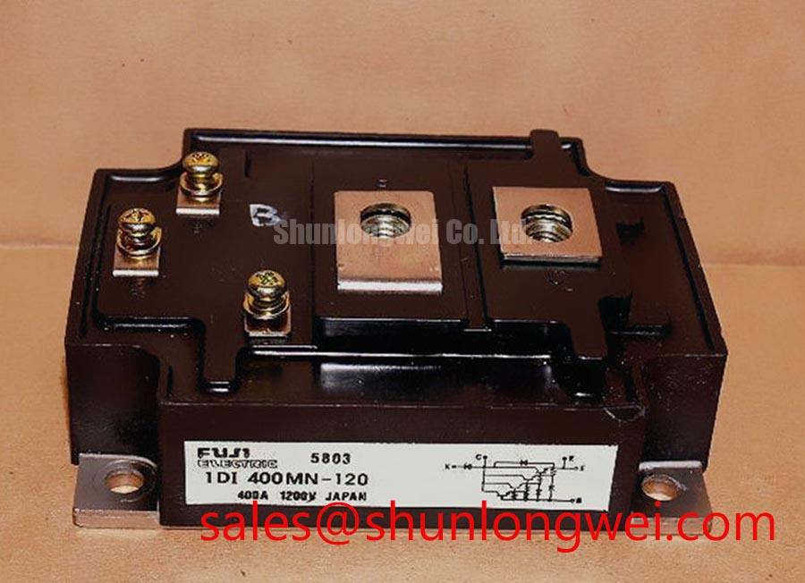
For continuous operation, assess conduction loss, switching loss, heatsink temperature, and airflow together. Increasing switching frequency changes the thermal burden, so the operating point must follow measured losses and the documented thermal path. When comparing 1DI400MN-120 with 1DI400D-100, check device technology, terminal geometry, drive requirements, safe operating area, and mounting compatibility before considering interchangeability.
Preventing Spurious Faults: DC-Bus Low-Inductance Laminated Busbar Design Guidelines for 1DI400D-100
Trace the commutation loop between the DC-link capacitor, switching device, and return path before changing suppression components. Engineering Calculation: the first-order relationship Vpeak ≈ VDC + Lσ × |di/dt| explains how stray inductance adds turn-off voltage stress, where |di/dt| is the magnitude of the current fall rate; measured waveforms must also account for ringing and the actual clamp network.
Keep outgoing and return conductors close where insulation requirements permit, and minimize unnecessary loop area. Select snubber capacitance and damping from the measured transient, pulse energy, and component ratings. Check the voltage directly across the relevant device terminals using a suitable probe arrangement, since measurement-loop pickup can resemble switching overshoot.
💡 Pro Tip: Keep corresponding busbar paths geometrically balanced, then verify turn-off voltage margin with a controlled switching test before increasing load.
Review base-current delivery, reverse-drive behavior, and driver-return routing against the Darlington circuit. Avoid importing IGBT Miller-plateau or active gate-clamp settings into this assessment. The 1DI400MP-050 can be examined alongside the system schematic as another device comparison, without assigning it a rectifier or companion-switch role. Fuji Electric Europe Semiconductor & Power Electronics provides manufacturer context; Fuji’s RC-IGBT modules represent a separate technology family.
Benchtop Waveform Tuning: Mitigating Stress via Thermal Interface Material Thickness Uniformity on 1DI400D-100
Inspect heatsink flatness and the module mounting surface before applying thermal interface material. Design Consideration: use the interface material’s application instructions together with the module mounting specification to control coverage and assembled thickness. Excess material, trapped debris, or incomplete wetting can impair heat transfer.
Follow the prescribed tightening sequence and torque, checking that the module seats evenly. Avoid using mounting pressure to force a distorted surface flat. During a controlled load ramp, track case temperature, cooling conditions, and electrical waveforms together so that a thermal change is not confused with a driver adjustment.
When evaluating compatibility with a utility-scale centralized battery energy storage PCS, designers should verify the converter topology, base-drive capability, blocking requirements, and cooling arrangement. Record the installed interface material, fastening procedure, and stabilized temperatures so subsequent maintenance can reproduce the assembly conditions.