
Content last revised on June 17, 2026
Fuji 2DI200A-050P Darlington Transistor Module | 500V 200A Dual Switch
How do engineers maintain efficiency in high-current switching systems when gate drive power is limited? This is a frequent challenge in legacy industrial upgrades and specific DC chopper designs. The Fuji 2DI200A-050P provides a robust answer through its dual Darlington configuration, offering high current gain that significantly reduces the complexity and power requirements of the driving stage. Unlike high-frequency IGBTs that might require complex negative gate voltages for stability, this 500V 200A power transistor module prioritizes ruggedness and ease of integration for low-to-medium frequency applications.
Highlight Overview
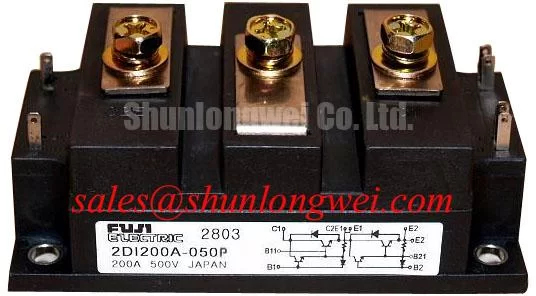
The Fuji 2DI200A-050P is a high-power dual Darlington transistor module designed for reliable current management in industrial environments. It delivers 500V of collector-emitter voltage and a continuous collector current of 200A, making it a cornerstone for Variable Frequency Drive (VFD) braking units and high-capacity DC power supplies. By leveraging a high DC current gain (hFE), it allows for simplified Gate Drive logic while maintaining high isolation standards. For 400V systems prioritizing thermal margin and drive simplicity, this 500V module remains a technically superior choice for long-term operational stability.
Frequently Asked Questions
How does the high DC current gain of the 2DI200A-050P simplify base drive requirements?
The 2DI200A-050P features a Darlington configuration with a minimum hFE of 100. This high gain means that to switch a 200A load, the base drive circuit only needs to provide a fraction of the current compared to a standard bipolar transistor. This allows for the use of smaller, less expensive drive components and reduces the overall heat dissipation within the control circuitry, effectively bridging the gap between low-power logic and high-power switching.
What is the significance of the 500V Vceo rating in industrial inductive load switching?
The 500V rating provides a critical safety buffer for 200V and 240V AC rectified lines. When switching inductive loads like motors or large solenoids, voltage spikes (L di/dt) are inevitable. The voltage ceiling of the 2DI200A-050P ensures that these transients do not exceed the SOA (Safe Operating Area), preventing catastrophic dielectric breakdown during high-speed turn-off transitions.
Key Parameter Overview
Decoding the Specs for Enhanced Thermal Reliability
| Parameter | Official Value | Engineering Significance |
|---|---|---|
| Collector-Emitter Voltage (Vces) | 500V | Ensures robust performance on 220V/240V AC rectified DC buses. |
| Collector Current (Ic) | 200A | Designed for heavy-duty Motor Drive and industrial heating. |
| Collector-Emitter Saturation Voltage (Vce(sat)) | 2.0V (Typical) | Determines conduction losses; essential for calculating Thermal Management. |
| DC Current Gain (hFE) | 100 (Min) | Reduces the drive current requirement, simplifying the Gate Drive. |
| Isolation Voltage (Viso) | 2000V AC (1 min) | Guarantees safety and prevents ground loops in multi-module systems. |
Download the 2DI200A-050P datasheet for detailed specifications and performance curves.
Technical Deep Dive
Analyzing the Dual Darlington Topology for Low-Frequency Power Ruggedness
The internal architecture of the 2DI200A-050P utilizes a cascaded transistor pair. Think of this as a "current amplifier" where the first transistor amplifies the base signal to drive the much larger second power transistor. This physical structure is analogous to a mechanical lever; a small input force (base current) manages a massive load (200A). While modern power systems often look toward IGBT vs MOSFET vs BJT trade-offs, the Darlington BJT in the 2DI200A-050P excels in applications where the switching frequency is below 10kHz, providing a linear saturation characteristic that is highly predictable under high-surge conditions.
Furthermore, the Vce(sat) of 2.0V is optimized to balance conduction efficiency with Switching Loss. In high-current DC Chopper circuits, the ability of the Fuji 2DI200A-050P to stay within its Safe Operating Area during transient overloads is superior to many discrete alternatives. Designers must ensure that the Thermal Resistance interface is minimized using high-quality thermal paste to manage the dissipation of approximately 400W-600W under peak loads.
Application Scenarios & Value
Achieving System-Level Benefits in High-Current DC Control
In a high-fidelity engineering scenario, consider a Welding Power Supply or a large battery charging station. These systems often face massive current ripples and must survive harsh electromagnetic interference (EMI). The 2DI200A-050P, with its robust bipolar junction, is less sensitive to ESD and high-frequency gate ringing compared to sensitive MOS-gate devices. By utilizing this module, engineers can build more resilient power stages that withstand the "dirty" power environments typical of heavy industry. For systems requiring even higher current handling in similar architectures, the 1D600A-030 offers expanded capability, while those seeking modern IGBT equivalents might look at the QM150DY-H for different switching characteristics.
Common integration points include:
- DC Choppers for industrial electric vehicles.
- Braking units in Variable Frequency Drive (VFD) systems to dissipate regenerative energy.
- Uninterruptible Power Supplies (UPS) for high-reliability medical equipment.
- Induction heating power stages where 500V headroom is required.
For more detailed insights on maintaining these modules, refer to our guide on preventing failure modes in power semiconductors.
Frequently Asked Questions
How should the thermal resistance Rth(j-c) influence the selection of the heatsink?
The Rth(j-c) dictates how efficiently heat travels from the silicon junction to the module case. For a 200A module like the 2DI200A-050P, the junction temperature must be kept below 150°C. Engineers should calculate the total thermal path (Junction-to-Case + Case-to-Sink + Sink-to-Ambient) to ensure the heatsink can dissipate the calculated Vce(sat) losses without exceeding the Safe Operating Area.
What precautions are necessary when paralleling 2DI200A-050P modules?
Paralleling bipolar modules requires careful matching of Vce(sat) and hFE to prevent "current hogging," where one module carries more load due to a lower forward voltage drop. Using emitter balancing resistors and ensuring identical Thermal Management conditions across both modules are mandatory steps for reliability.
Is the 2DI200A-050P suitable for high-frequency PWM (>20kHz)?
Generally, no. As a Darlington transistor, the storage time and fall time are longer than those of modern IGBTs or MOSFETs. It is best suited for frequencies under 5-10kHz. For higher frequency requirements, the switching losses would likely lead to overtemperature unless the current is significantly de-rated.
From a maintenance perspective, when replacing these modules in aging equipment, always verify that the base drive resistors have not drifted in value, as the hFE-dependent nature of the 2DI200A-050P requires a precise current input for full saturation. Proper torque settings for the M5/M6 terminals are equally vital to prevent localized overheating at the electrical contacts.