

Content last revised on September 24, 2026
LM32007P Sharp Industrial LCD Display Inspection
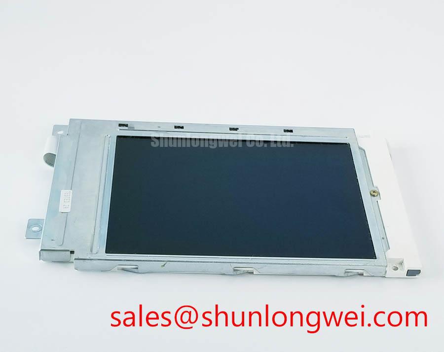
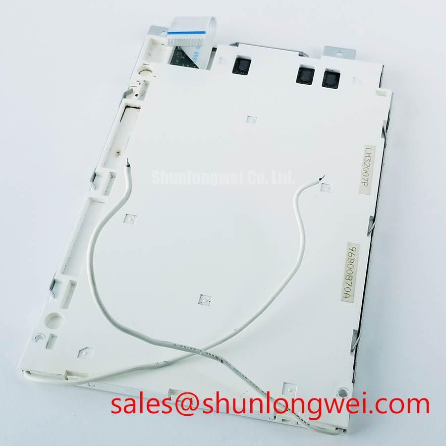
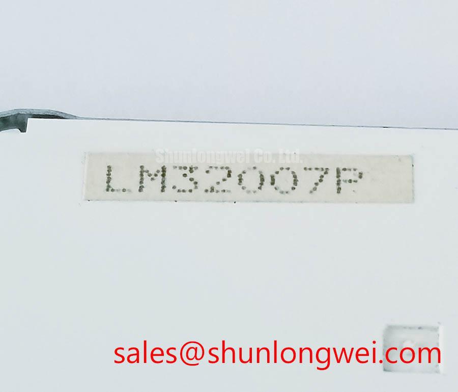
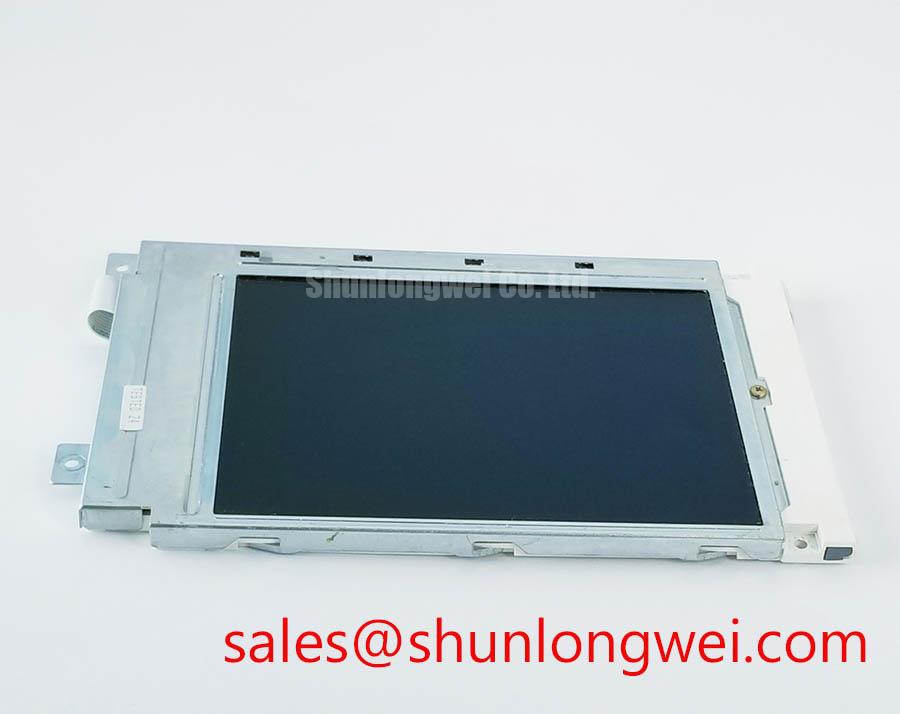
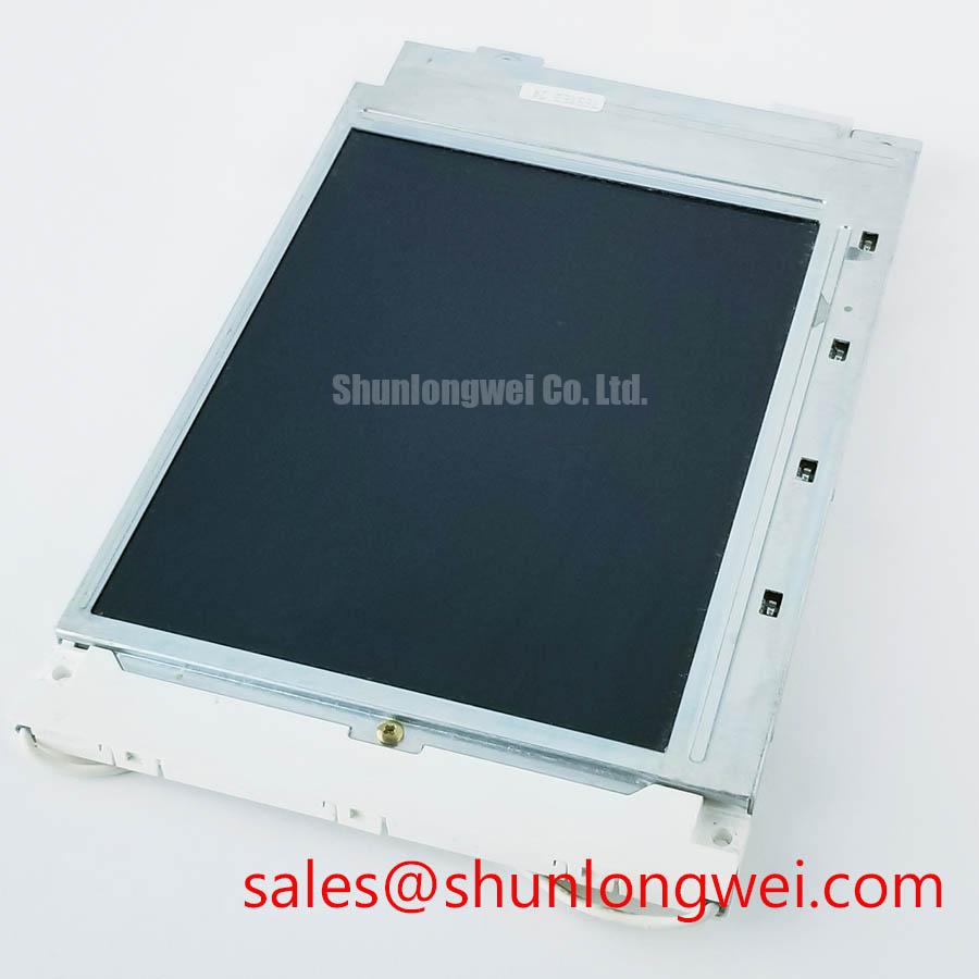
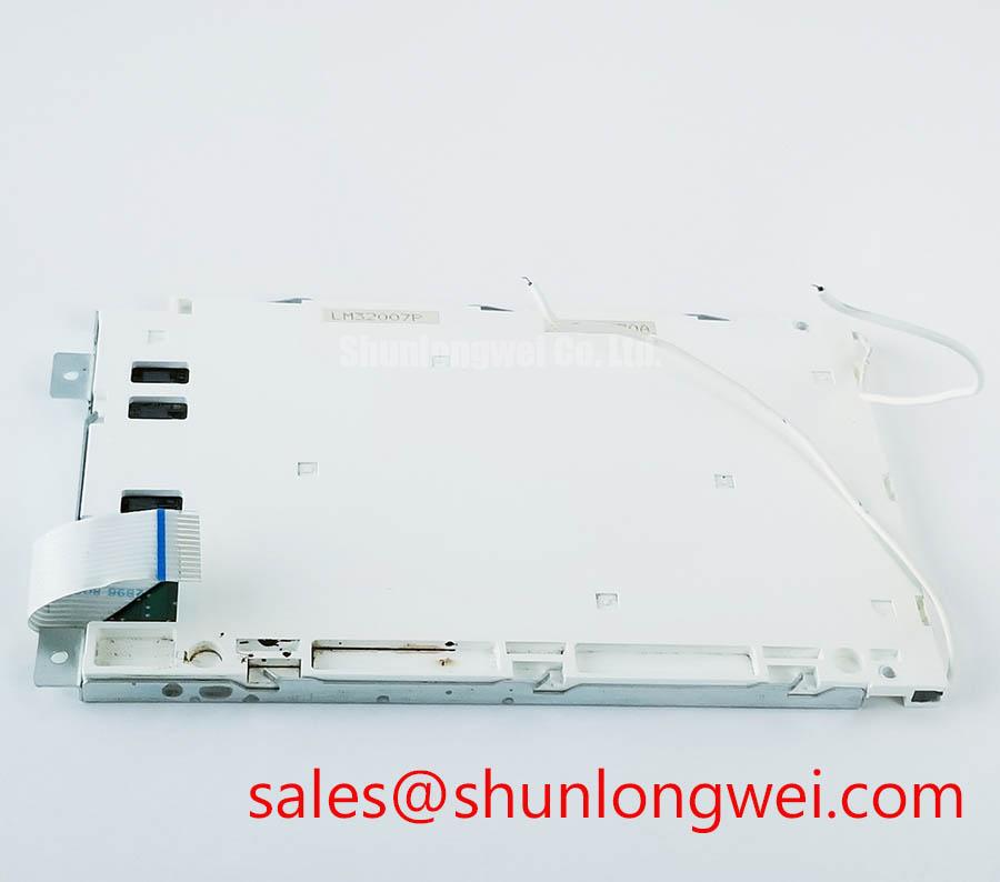
Inspect the LM32007P on an ESD-safe bench before applying power: check the TFT-LCD display module for glass-edge damage, frame distortion, connector contamination, and pressure marks, then compare the product marking with the approved equipment documentation. The available factory specification identifies this unit as a Sharp Industrial Grade LCD/HMI Panel with a TFT-LCD Display Module enclosure format and an Official Factory Spec Verified status. Electrical interface details, optical ratings, dimensions, and backlight data should be confirmed against the original panel documentation before installation.
For overseas maintenance teams, this verification is important because an industrial display replacement is determined by more than its visible screen area. Mechanical envelope, connector orientation, signal protocol, timing configuration, backlight control, mounting points, and host-system firmware all influence interchangeability. The LM32007P should therefore be evaluated as a complete display assembly within the target HMI, railway passenger information system, or cab signalling display rather than by appearance alone.
Incoming Benchtop Inspection: Glass-Driver Bond Integrity
Begin the incoming inspection with the display disconnected from the host controller. Use a clean, low-pressure visual inspection of the glass perimeter, flex-cable entry areas, connector contacts, and bezel. Do not press the active area to investigate a suspected line defect. A pressure-sensitive display fault can change during handling, making the original condition more difficult to assess.
A practical primary-colour test uses full-screen red, green, blue, black, and white images generated by the approved display controller. Examine the panel from a normal viewing position and then move the light source to approximately 45 degrees relative to the surface. This angled-light check can help separate a surface or backlight irregularity from a repeating line defect associated with the glass-driver connection area. A dark shadow or uneven glow that changes with the flashlight angle may require optical and mechanical investigation, while a fixed line that remains in the same pixel position across colour fields should be compared with the known-good signal path.
The product information supplied for the LM32007P does not publish a pixel count, active-area dimension, contrast ratio, viewing angle, coating specification, or bonded-driver construction detail. Those values must not be inferred from the model number. The integrator should record the original panel’s image geometry, connector arrangement, and controller settings before authorizing a replacement. If a service manual identifies a COG or TAB bonding area, inspect it without applying local pressure or solvent.
For a railway passenger information system or cab signalling display, the bench test should also include a uniform white field and a neutral grey field. These patterns make local brightness variation, image retention, nonuniform illumination, and unstable grey transitions easier to observe. Any observed defect should be documented by position, colour condition, temperature, controller state, and cable movement. This creates a repeatable comparison without assigning a single cause to the symptom.
Bench Tip: Disconnect power before inserting or removing the display cable, use ESD protection, and keep the flex connector fully aligned before locking it.
Dynamic Contrast Behaviour and Temperature Tracking
Dynamic image evaluation should be performed only after the LM32007P has reached a stable operating condition defined by the original equipment documentation. Run dark, mid-grey, and white test fields while observing the display from the intended installation direction. Changes in grey detail, colour balance, or visible contrast may be related to panel temperature, host timing, image processing, or backlight control, so the result should be compared with a known-good assembly whenever possible.
Sharp’s supplied product information for this listing does not specify whether the LM32007P uses TN, IPS, MVA, or another liquid-crystal mode. It also does not confirm a symmetric viewing cone of 85° in each direction, a contrast ratio above 500:1, or an anti-glare etching treatment. These characteristics must be verified from the original Sharp documentation or the equipment bill of materials rather than presented as fixed ratings for this model.
In a high-illumination control cabinet, the optical test should include the actual enclosure window, ambient lighting direction, and any protective cover. Direct sunlight can alter perceived black level and surface reflections even when the panel electronics are operating correctly. If the application requires a defined contrast value under a specified illumination level, the system engineer should measure the assembled display with calibrated equipment and use the result for acceptance criteria.
Signal integrity deserves the same discipline. If the host uses LVDS, the design team may evaluate differential-pair routing, return-current continuity, connector seating, and cable separation from switching conductors. A nominal 100 ohm differential impedance is a common interface design consideration, not an LM32007P factory specification in the supplied data. The host documentation must define the required impedance, termination, timing, and skew limits. Oscilloscope measurements should compare the suspect unit with the known-good signal path rather than relying on a visual symptom alone.
Gamma and T-CON behaviour should also be assessed at the system level. A display that shows correct full-colour fields but unstable grey steps may require inspection of source timing, power sequencing, gamma configuration, or controller compatibility. The LM32007P listing does not provide T-CON voltage rails, gamma reference values, start-up delays, or panel supply limits. The system integrator should verify every one of these items from the original panel documentation before applying power.
For background on panel selection, optical inspection, and industrial TFT integration principles, engineers can consult The Ultimate Guide to Industrial TFT LCD Technology.
Pixel Jitter and Horizontal White-Line Investigation Near Motor Drives
When the display is installed near a variable-frequency motor drive, begin diagnosis by separating the image source, display cable, backlight wiring, and cabinet power paths. Record whether the disturbance appears only during motor acceleration, at a particular image pattern, or when the cable is repositioned. This sequence helps identify an interference or connection-related condition without assuming that the panel itself is defective.
Use the shortest practical signal route and preserve the intended shield termination method specified by the equipment designer. A shielded FFC or LVDS cable should not be folded sharply against a metal edge, placed in parallel with high-current switching conductors for an unnecessary distance, or left with a loose connector latch. The correct grounding arrangement depends on the host chassis, cable construction, isolation strategy, and EMC design. The LM32007P factory information supplied here does not define a 360-degree shield termination, ferrite type, or common-mode attenuation requirement.
If horizontal white bands or pixel jitter occur, first compare the display with a known-good controller and cable. Then inspect connector alignment, cable seating, supply stability, and timing signals while the motor drive changes state. An oscilloscope can help identify whether the disturbance is present at the source, introduced along the cable, or visible only after the panel receives the signal. Avoid treating a single visual pattern as proof of a panel-level fault.
Backlight modulation should be evaluated separately from image data. The supplied LM32007P specification does not confirm an LED backlight architecture, PWM input, PWM frequency range, dimming duty-cycle linearity, or audible-noise performance. If the original system uses PWM dimming, the replacement controller must be checked against the original backlight driver documentation. A suggested test frequency or duty cycle would be a system-level starting point, not an official rating for this display.
For maintenance planning, record the disturbance together with motor-drive state, cabinet temperature, cable routing, display pattern, and backlight setting. This evidence is more useful than replacing the panel repeatedly without confirming whether the interference is generated upstream. Where a same-size or same-resolution service option is being evaluated, engineers may review LM190E08-TLG6 as a separate component and verify its full mechanical and electrical compatibility independently.
Flush-Mount Open-Frame Bezel Integration and Shock Isolation
Before flush mounting the LM32007P, compare the replacement module with the equipment’s bezel opening, rear clearance, connector access, cable bend path, and fixing locations. The available factory data classifies the unit as a TFT-LCD Display Module but does not publish the outer dimensions, active-area dimensions, mounting-hole pattern, bezel thickness, mass, or allowable fastening load. These measurements should be taken from the original assembly drawing or confirmed with the panel documentation.
The bezel should support the intended frame area without pressing on the active glass. Mechanical loading must remain distributed through the approved mounting structure, while the cable should have sufficient clearance to avoid tension at the connector. If a gasket is used for vibration, dust, or shock control, its compression and material suitability are system design considerations that require validation in the completed enclosure. Do not treat a generic gasket dimension as an LM32007P factory requirement.
Fastener selection and torque should follow the equipment manufacturer’s mechanical drawing. The supplied LM32007P information does not specify M3 fastener torque, cross-pattern tightening limits, chassis flatness, or shock qualification. Engineers should verify the assembled bezel for local stress by running a powered uniform-field test before and after tightening. A change in dark-field uniformity after installation may indicate mechanical loading, optical pressure, cable interference, or another assembly condition requiring controlled investigation.
Backlight service life should also be handled carefully. No LM32007P LED-backlight lifetime, brightness-retention curve, constant-current requirement, thermal derating profile, or 50,000-hour performance value is included in the supplied official parameters. If the original equipment requires a specific brightness-retention target, the system owner should obtain the applicable Sharp documentation and validate the complete backlight driver, enclosure temperature, and operating profile. A display module alone cannot establish the lifetime of the installed system.
For railway passenger information equipment and cab signalling displays, final acceptance should combine the visual test patterns, signal-integrity check, connector inspection, enclosure fit, and operating-temperature observation. The correct replacement decision remains dependent on the original system documentation and measured interface compatibility. The documented product identity for this listing is Sharp LM32007P, an Industrial Grade LCD/HMI Panel supplied as a TFT-LCD Display Module.