Content last revised on November 21, 2026
KCG057QVLDG-G760 Display Identification and Initial Checks
With the equipment isolated from power, inspect the display cable latch and connector seating before investigating a black screen on the KCG057QVLDG-G760. Record whether the screen is completely dark, faintly illuminated, or showing an image only under external light; these observations help separate illumination problems from missing image data without prematurely condemning the panel.
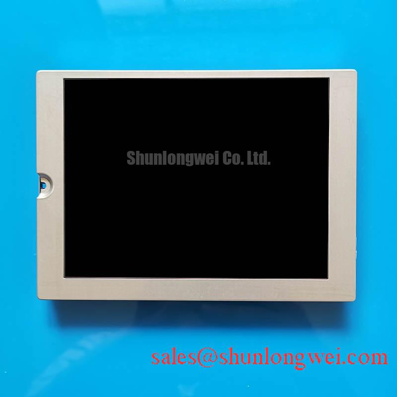
The Kyocera display has a Diagonal Size: 5.7 inch, Resolution: 320 x 240, and Interface: TTL / CMOS. Its identification is Manufacturer: Kyocera and Part Number: KCG057QVLDG-G760. It is a Color LCD Display Module. For electrical integration, obtain the model-specific supply requirements, connector drawing, signal timing, and backlight requirements from the original panel documentation before applying power.
Suppressing Localized Thermal Gradients to Prevent Chronic Optical Yellowing (Color Shift)
Compare discoloration near the display edges with the temperature distribution of the surrounding enclosure after normal operation. A warm region beside a power supply, illumination driver, or enclosed cable bundle warrants investigation, but yellowing alone does not identify the affected optical material or establish heat as the sole cause.
Design Consideration: reduce concentrated heat loading around the panel rather than adding an unverified heat spreader directly to its frame. Where enclosure rails provide a thermal path, evaluate their contact locations, electrical clearances, and expansion behavior against the module mounting drawing. A rail that improves heat transfer but distorts the display assembly can introduce a different optical defect. Compare uniform test fields before and after the enclosure reaches its normal operating condition.
Evaluate brightness drift using repeatable image content, brightness commands, ambient conditions, and measurement position. Separate illumination loss from changes caused by viewing angle, contamination, or a protective window. Neither an illumination lifetime nor an optical material composition should be assigned to this model from its diagonal size or part-number family. A brightness-maintenance claim also needs its stated temperature, drive conditions, and endpoint definition; it is not interchangeable with equipment MTBF.
For broader manufacturer context, Kyocera Industrial TFT-LCD Display Technologies provides information about display technologies. Use the model-specific electrical specification, rather than a general technology description, when determining permissible operation.
High-Humidity Storage Margins (60°C / 90% RH) & Delamination Prevention Protocols
Treat 60°C / 90% RH as an environmental test condition requiring explicit manufacturer authorization, not as an established storage rating for the KCG057QVLDG-G760. Before powering a panel transferred from a cold store into a warmer workshop, allow it to equilibrate and inspect the connector region and viewing window for condensation.
Design Consideration: investigate edge haze, bubbling, or apparent layer separation under consistent lighting before changing mounting pressure or cleaning methods. Surface contamination, moisture on a cover window, and an internal optical defect can produce superficially similar appearances. Photograph the affected region with the display off and with uniform fields displayed, then compare its position relative to the enclosure and active image area.
For cold-start evaluation, observe moving edges and changing text separately from static-image contrast. Liquid-crystal response generally changes with temperature, so sluggish transitions need comparison with the equipment’s approved operating conditions and a known-good assembly. Do not compensate by increasing an unidentified supply or altering controller timing without validating the complete interface. Avoid imposing an assumed industrial thermal-cycle range on this particular panel.
Inspect cable routing where temperature changes and enclosure movement can load the connector. Support the harness so that its weight does not pull on the latch, and avoid repeatedly folding a flexible cable at the same crease. Bend limits and insertion-cycle limits belong to the actual cable and connector specification, not to a generic LCD maintenance rule.
Flashlight Dark-Shadow Optical Diagnostic to Isolate Logic vs. Backlight Failure Modes
Shine a flashlight obliquely across the dark screen while the controller displays a known image. A faint, changing image supports further investigation of the illumination path, but it does not by itself prove that the panel logic, image timing, or backlight assembly is fully functional.
Engineering Recommendation: compare red, green, and blue fields, followed by text or a grid, using the equipment’s supported diagnostic mode. Note whether defects remain at fixed screen coordinates, follow changing content, or change when the external harness is correctly reseated. Persistent lines can involve the signal path, connector, controller, or panel; their appearance does not establish a particular internal bond failure.
Field Alert: Isolate equipment power and allow stored energy to discharge before disconnecting or reseating the display interface.
At the controller, compare supply stability, enable sequencing, and TTL / CMOS waveforms with the approved schematic and a known-good signal path. Avoid treating the interface name as a pinout or logic-voltage specification. If brightness modulation is present, examine its waveform and the visible result throughout the supported adjustment range; suitable modulation behavior depends on the actual driver, illumination system, and equipment requirements.
When checking related display options, KCG057QV1DB-G520 is a separate model for documentation comparison, not an established auxiliary driver for this panel. Compare its power and interface requirements independently. For a surgical-navigation or ultrasound-terminal repair assessment, the equipment manufacturer must also establish optical suitability and system compatibility; these basic panel specifications do not establish diagnostic-display performance.
Preventing Localized Light Guide Plate (LGP) Compression Warp on Dark Screen Fields
Compare a dark field with the panel supported without bezel pressure, then repeat after normal enclosure assembly. A patch that changes with assembly pressure suggests a mechanical contribution, but does not identify a particular internal light-guide structure or material.
Design Consideration: check bezel clearance, mounting-surface flatness, cable trapping, and uneven gasket loading before changing fastener settings. Use the equipment’s specified hardware and tightening procedure; a generic screw torque is not a verified limit for this module. Maintain the intended support points without transmitting enclosure distortion into the display face.
For replacement assessment, compare KG057QVLCD-G050 against the original assembly drawing and electrical documentation rather than assuming interchangeability. Matching nominal size or resolution does not establish matching mounting geometry, connector assignment, timing, or illumination requirements.
If the installation includes a separate touch assembly, evaluate its mounting and input behavior independently of the LCD image. A Guide to Resistive, Capacitive, and IR Touchscreens provides useful technology context without establishing this panel’s touch configuration. After reassembly, check dark-field uniformity, moving content, connector retention, and touch response where fitted, with the enclosure secured in its normal operating position.