Content last revised on September 13, 2026
Sharp LM3219T Inspection and Integration
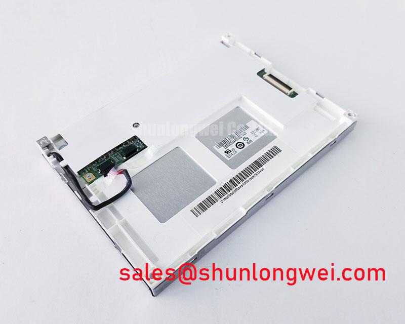
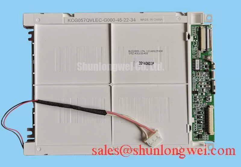
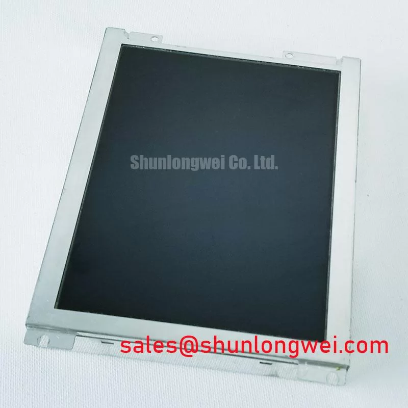
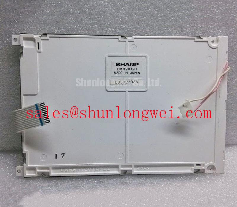
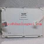
Begin incoming inspection by checking the Sharp nameplate and LM3219T identification, then examine the TFT LCD display module under controlled illumination for cracked glass, bezel distortion, connector damage, and visible contamination. Record the condition before applying power, and confirm the replacement against the original panel documentation because the available factory information identifies this unit as an Industrial Grade LCD/HMI Panel with a TFT-LCD Display Module construction, but does not publish every electrical, optical, or mechanical integration value required for a system-level substitution.
The Sharp LM3219T is evaluated here as an industrial LCD display component for equipment such as operator interfaces, monitoring panels, and high-voltage substation protection or SCADA dispatch consoles. Its documented identity is the primary acceptance point: manufacturer Sharp, product category Industrial Grade LCD/HMI Panel, package or enclosure description TFT-LCD Display Module, and available factory identification information. Panel dimensions, native resolution, interface assignment, supply voltage, backlight configuration, brightness, viewing angle, and temperature limits should be confirmed from the original panel documentation before installation.
| Inspection Item | LM3219T Information Available for Evaluation | Integration Action |
|---|---|---|
| Manufacturer | Sharp | Match the equipment service record and panel marking |
| Model | LM3219T | Confirm the complete model code before replacement |
| Product category | Industrial Grade LCD/HMI Panel | Evaluate for the intended HMI or monitoring function |
| Module construction | TFT-LCD Display Module | Verify bezel, mounting, cable, and controller compatibility |
| Specification status | Factory identification available | Use the original equipment documentation for missing values |
Diffuser Film and Prism Sheet Thermal Buckling Prevention under Continuous Full Duty Operation
For a display operating continuously in a control cabinet, the incoming inspection should begin with the optical stack and its surrounding mechanical frame. Look across a white test image, a black test image, and several mid-tone images from a normal viewing position. Uneven illumination, edge darkening, local bright patches, or lines that change when the chassis is gently stressed may require separation of optical, mechanical, and signal investigations. These observations should not be assigned to a particular internal film, guide plate, or adhesive unless the Sharp service documentation confirms that construction.
Thermal management is a system-level design consideration rather than a published LM3219T factory rating in the supplied specification context. Designers should examine heat sources around the panel, including processor boards, DC converters, LED driver circuits, and enclosed cable bundles. A metal support rail or heat-spreading structure may be considered where it can reduce localized temperature concentration without transferring chassis stress into the display glass. The final arrangement should be validated with the installed enclosure, backlight setting, ambient conditions, and actual duty cycle.
Do not clamp the perimeter simply to remove a visible optical irregularity. Excessive or uneven frame pressure can create a temporary visual change during assembly and a persistent mura pattern after thermal cycling. The bezel should support the module evenly while leaving the display surface free from point loading. Gaskets may be used as a Design Consideration for dust control and vibration isolation, but their compression, material selection, and sealing performance must be determined by the equipment designer and enclosure requirements.
Claims about L70, B50, optical film composition, or long-term yellowing performance require a relevant Sharp datasheet or qualified test report. They are not inferred from the LM3219T model designation. For a broader explanation of panel selection, operating principles, and integration checks, engineers can consult The Ultimate Guide to Industrial TFT-LCD Technology.
Controlled Differential Flex Routing to Suppress High-Frequency Jitter
Before connecting the LM3219T to a controller, identify the cable type, connector keying, pin assignment, signal convention, and backlight arrangement from the original panel documentation. The supplied factory context does not confirm whether this particular assembly uses a specific LVDS, TTL, JEIDA, or VESA mapping, and it does not confirm a logic supply value. The system integrator should verify the required supply voltage from the original panel documentation rather than applying a generic display voltage.
When a differential display interface is confirmed by the equipment drawings, controlled routing is an Engineering Recommendation. Keep each differential pair together, avoid unnecessary changes in reference plane, and limit connector transitions that can add discontinuity. The target impedance, pair-to-pair skew, transmitter timing, and receiver setup or hold requirements must come from the applicable panel and controller specifications. Values sometimes used in general LVDS design cannot be presented as official LM3219T parameters.
Power sequencing deserves a separate bench check. Observe the logic supply rise, display enable signal, clock activity, and data activity with an oscilloscope while the module is connected to the intended controller. A white screen, delayed image, split image, or intermittent startup may involve timing, mapping, cable contact, controller configuration, or power integrity. Verify the known-good signal path before replacing the panel, and compare waveforms at the controller output and panel input when safe probing access is available.
Power-down behavior should also be checked. Remove the display enable command according to the original system sequence, then observe whether the image disappears cleanly or leaves a residual pattern. A remaining image can be associated with an incorrect shutdown sequence, stored charge, controller behavior, or a panel-side fault. The correct response is to compare the service unit with a known-good assembly and follow the original controller documentation, not to impose an unverified timing prescription.
Bench Tip: Use ESD protection and lock the flex cable squarely into its connector before applying power; an incompletely seated cable can imitate a panel or mapping fault.
Suppressing Pixel Jitter and Horizontal White Lines near Adjacent Motor Drives
When the LM3219T is evaluated beside variable-frequency motor drives or other high-current switching equipment, first reproduce the symptom with the panel installed in its normal cabinet position. Note whether the disturbance follows motor start, speed changes, relay operation, or backlight transitions. Capture the display supply and interface activity at the same time if the test setup permits. This approach helps distinguish conducted supply disturbance, radiated coupling, grounding interaction, and a panel or controller fault without assigning a single cause too early.
Cable routing is a Design Consideration. Keep display flex cables away from high-current motor conductors and switching nodes where the cabinet layout allows. If a shielded cable is part of the approved system design, terminate and bond it according to the controller, chassis, and safety architecture. A shield that is connected inconsistently can produce a different result from a shield that is correctly integrated. The suitability of a 360-degree shield termination, ferrite component, or common-mode filter depends on the cable construction, frequency spectrum, enclosure bonding, and required safety clearances.
Do not assume that a ferrite will correct every horizontal line or pixel jitter problem. First inspect connector retention, cable folding, reference ground continuity, supply ripple, and controller configuration. Then compare the affected display with the same panel driven from a clean test source. If the defect disappears on the test source, investigate the cabinet topology and signal return path. If it remains, inspect the panel assembly, cable, and controller independently.
For a confirmed high-speed differential interface, the design team should verify characteristic impedance, pair matching, return-current continuity, and clock-to-data timing against the actual controller and panel documentation. These are system design conditions, not published LM3219T performance guarantees. EMC compliance must be assessed at the complete equipment level; a display module by itself does not establish compliance with CISPR, EN 55011, or another complete-system standard.
Flush Mount Open Frame Bezel Integration and Perimeter Gasket Shock Isolation
Measure the original cutout, mounting points, connector clearance, cable bend path, and visible display opening before preparing a replacement bracket. The available LM3219T specification information does not state the outer bezel envelope, active-area dimensions, mounting-hole pattern, or fastener specification. Those values must be taken from the original equipment drawing or verified by direct mechanical inspection. A panel that appears visually similar can still fail because the connector exits into a frame member or the bezel transfers pressure into the glass.
Flush mounting should use an even support surface with a controlled gap around the module. The enclosure designer should account for cabinet movement, vibration, thermal expansion, and service removal. A perimeter gasket can help isolate vibration and limit dust entry when selected for the actual enclosure, but gasket thickness and compression are system-determined. Avoid using the fasteners to force the display into alignment. Correct the bracket or bezel geometry first, then tighten the assembly progressively in a cross pattern when the equipment drawing specifies that method.
Fastener torque is a Design Consideration that must follow the chassis material, thread size, washer arrangement, and display manufacturer’s mechanical documentation. The supplied LM3219T data does not establish a model-specific torque limit. Excess torque can distort the bezel or create localized pressure, while insufficient retention can allow movement and cable fatigue. After assembly, repeat the white, black, and mid-tone image checks at operating temperature and inspect the screen while applying only the normal service-level cabinet vibration.
For a potential high-voltage substation protection or SCADA dispatch console installation, verify viewing position, ambient light, cabinet sealing, grounding, controller compatibility, and service access as one integrated evaluation. The Sharp LM3219T should be released for that equipment only after its electrical and mechanical values have been matched to the original panel record. Where a same-class replacement assessment is required, engineers may also review LM190E08-TLG6 as a separate compatibility reference, subject to independent confirmation of dimensions, interface, optical performance, and system requirements.