

Content last revised on September 24, 2026
Preventing Frame Lag & Image Smearing in Cryogenic Storage & Outdoor Industrial Facilities
Before evaluating an LM64P70 for an enclosure exposed to low ambient temperature, observe the panel only after the cabinet has reached its actual operating condition. Liquid-crystal response can slow as ambient temperature falls, and operators may describe the result as frame lag, trailing images, or image smearing. These visual effects should not be treated as proof of a panel fault without comparison against the original display, controller output, and environmental conditions.
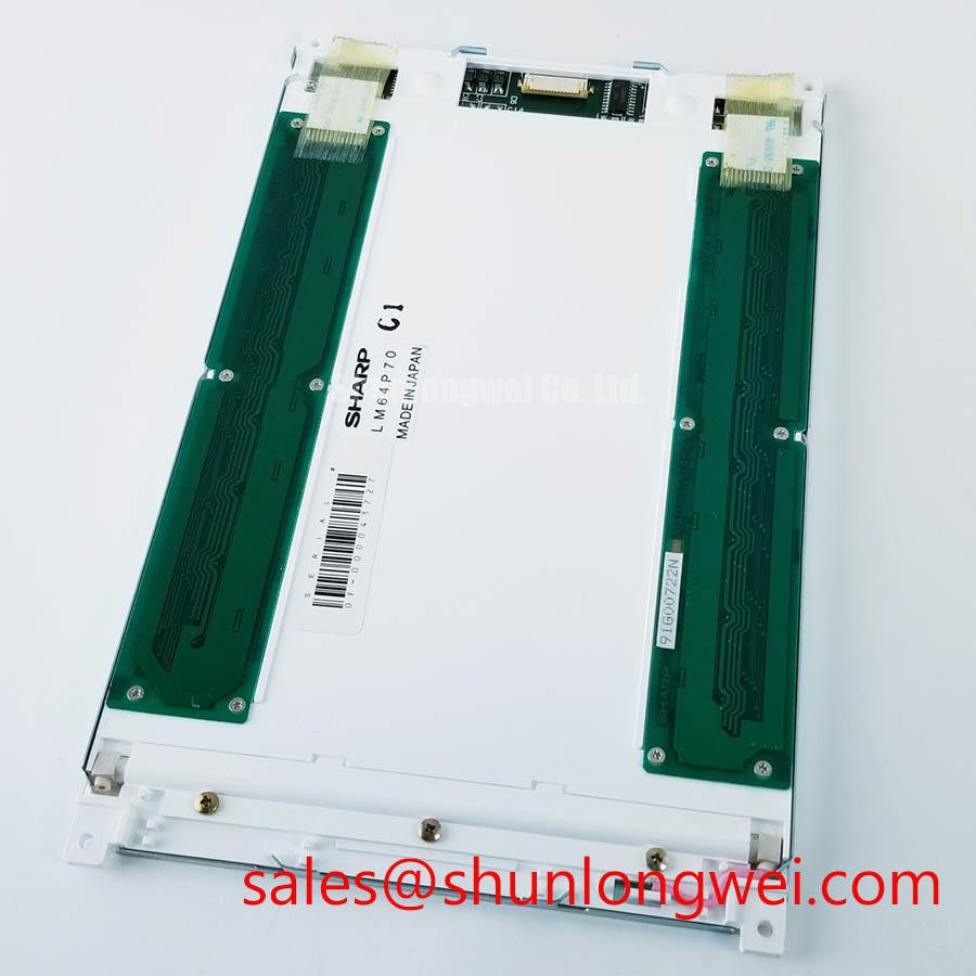
The supplied product information confirms that LM64P70 is a Sharp TFT-LCD module, but it does not provide an official operating-temperature rating. Conditions such as −30°C to +85°C therefore cannot be stated as an LM64P70 factory rating. They are system-level environmental conditions that must be checked against the original Sharp documentation, cabinet thermal survey, and the temperature specification of the replacement display assembly.
For outdoor industrial facilities or refrigerated process areas, Design Consideration begins at the enclosure rather than at the screen face. Review whether the panel perimeter is protected from dust ingress, water vapour, and repeated condensation. A loose bezel gasket can permit contaminants to migrate behind the viewing window, while uneven clamping can introduce visible pressure zones that are often mistaken for permanent optical damage. Allow cabinet materials and the display frame to move with temperature changes rather than using the enclosure cutout to force the module into position.
Direct sunlight introduces a separate readability question. A contrast target such as 500:1 at 50,000 lux must not be assigned to LM64P70 without an official optical datasheet. For a substation protection terminal installed near a window, yard-facing control room, or outdoor service shelter, engineers should measure the actual incident light at the installed viewing angle and assess the complete assembly, including the front filter, window glass, glare control, and operator position. Any anti-glare treatment must also be verified from the original panel or enclosure specification rather than assumed from the TFT-LCD classification.
Where low-temperature image behaviour is observed, isolate the visual symptom before changing components. Confirm that the controller is delivering stable image data, allow the assembly to equilibrate, and compare the same screen pattern at different cabinet temperatures. If an enclosure heater, thermostat, or airflow path is present, its behaviour belongs to the host system validation plan. It is not an LM64P70 factory feature unless documented in the original equipment records.
For a same-family comparison during a service evaluation, the LM64P10 can be reviewed as a separate display option. Mechanical fit, connector assignment, timing, supply requirements, brightness behaviour, and controller compatibility must be verified independently. Matching a product family name or nominal display class alone does not establish interchangeability.
Incoming Benchtop Inspection: Display Bond and Module Integrity
Use a controlled bench setup before fitting LM64P70 into a cabinet. Start with the display disconnected from the host system and examine the connector area, flex sections accessible from the exterior, display border, and module frame under diffuse light. Look for handling stress, displaced protective films, corrosion residue, warped mounting surfaces, or evidence that the display has been constrained by the original chassis. These observations identify conditions requiring closer evaluation; they do not, by themselves, establish an internal failure mechanism.
A practical primary-colour test can help separate image-path symptoms from illumination symptoms. Feed a known-good source with full red, full green, full blue, neutral grey, black, and white fields, using only the interface configuration confirmed for the original equipment. Observe whether any line, column, colour imbalance, flicker, or uneven area remains fixed across different test patterns. A defect that follows the input source, cable movement, or controller output needs investigation beyond the panel itself.
A flashlight check at approximately a forty-five-degree viewing angle can be useful when a dark display still appears to have an image. In a controlled and safe bench condition, a faint image visible through external illumination may indicate that image generation and illumination require separate checks. It does not prove a backlight fault, nor does a dark region prove a driver-bond issue. Confirm the power sequence, source signals, and any dedicated illumination circuitry against the original equipment documentation.
The official information supplied for LM64P70 does not identify the backlight type or publish a brightness-maintenance figure. A statement such as 50,000 hours to 50% brightness must therefore not be presented as an LM64P70 specification. If a maintenance plan uses brightness trend data, it should be based on the original panel documentation or a traceable system-level test method. Constant-current driver operation can be relevant to some display illumination systems, but the required driver arrangement for this model must be verified from the original panel documentation.
⚠️ Maintenance Note: Inspect cabinet cooling paths and display gasket condition during scheduled service, because trapped heat and moisture can affect the complete display assembly even when the screen surface appears normal.
Do not apply pressure to the active viewing area while investigating a visual symptom. Instead, support the module by its approved frame locations and use stable test patterns. If the original equipment includes a touch overlay, determine whether it is a separate assembly before testing touch performance. The available factory information does not confirm a resistive or capacitive touch function for LM64P70, so glove operation, wet-surface sensitivity, and touch-controller settings must be checked at the equipment level.
Industrial EMI Noise Immunity, Chassis Shielding Continuity & Common-Mode Ferrite Chokes
When horizontal noise bands, intermittent pixel movement, or image jitter appear near inverter-fed motors, begin at the cabinet cable route and shield termination. Variable-frequency drives, servo systems, contactors, and power conversion equipment can create an electrically noisy environment, yet a visible display disturbance does not identify a single cause. The display module, cable path, source board, grounding scheme, supply regulation, and enclosure bonding all require inspection.
LM64P70 is identified as a TFT-LCD display module, but its official interface type is not included in the available factory information. Do not assume TTL, LVDS, FFC, or another connector arrangement from the model name. The system integrator should verify the required signal interface, connector pinout, supply voltage, data timing, and power sequencing from the original panel documentation before probing signals or selecting a cable assembly.
If the confirmed host interface uses differential video signalling, maintaining the intended controlled impedance is a Design Consideration. A nominal 100 Ω differential path is commonly associated with certain differential interfaces, but it is not an LM64P70 official specification unless identified in the relevant Sharp documentation. Cable length, pair routing, transmitter capability, receiver requirements, and clock-jitter tolerance remain system-determined and should be validated with measurements against a known-good signal path.
Shield continuity should be assessed from source enclosure to display enclosure, including the practical quality of chassis contact at cable entry points. A 360-degree shield termination is often considered where the confirmed cable design and host equipment support it, because a long unbonded shield tail can reduce high-frequency shielding effectiveness. Common-mode ferrite components can also be evaluated where conducted or radiated coupling is suspected, but their selection should follow the actual noise spectrum, cable current, safety requirements, and system verification results.
Do not claim that the display module independently meets a complete equipment EMC standard. EMC compliance belongs to the finished system and depends on enclosure construction, wiring, power conversion equipment, cable shielding, grounding, and tested operating modes. For structured diagnostic practice covering industrial screen, cable, enclosure, and environmental interactions, see Industrial Display & HMI Solutions.
In cold environments, slow liquid-crystal response can coexist with electrical noise symptoms. Verify each condition separately. Observe the display with stationary test images, compare behaviour with motors stopped and running where safe, and capture source signals using appropriate test equipment. A heater-strip control strategy, if installed in the host cabinet, should be evaluated as a system function with condensation control and temperature sensing considered together.
Where the original system uses a separate display or illumination-related device, the LMS700KF01-001 may be relevant for neutral system-level review. Its role, electrical characteristics, and compatibility must be established from its own documentation and the host circuit, not inferred from its presence beside LM64P70 in a product evaluation.
Thermal Expansion Clearance Sizing across Heavy Industrial Metal Enclosure Cutouts
Before tightening an LM64P70 into a heavy industrial enclosure, inspect the cutout for burrs, paint build-up, distorted corners, and surfaces that can bear on the display face rather than its approved mounting frame. A panel that sits flat on the bench can become optically uneven once it is forced into a non-planar cutout. Localized bezel loading may appear as light or dark mura, colour shift, pressure marks, or an area that changes when the cabinet door is closed.
The supplied factory information does not provide LM64P70 bezel dimensions, mounting-hole positions, fastener sizes, or torque limits. A cross-pattern torque value of 0.35–0.45 N·m for M3 hardware is a General Industry Design Consideration in suitable assemblies, not an LM64P70 factory requirement. The installer should use the fastening method specified by the original equipment manufacturer and tighten gradually in an alternating pattern so the frame seats evenly without transferring stress into the active display area.
Clearance around the outer bezel must be determined from the official mechanical drawing and the actual enclosure material. Steel cabinet faces, aluminium panels, painted cutouts, front windows, foam gaskets, and retaining brackets can expand differently with temperature. The objective is to prevent edge binding while maintaining the intended environmental seal. If the enclosure includes a front cover or touch overlay, check that it does not press unevenly against the display during thermal cycling or door movement.
Thermal management must also be assessed as an assembly issue. Restricted airflow, nearby power supplies, and enclosed control cabinets can create local heating around the display frame and source electronics. Do not assign a permitted thermal limit to LM64P70 without the original specification. Instead, measure cabinet temperature under representative load, inspect airflow paths, and check whether the host system’s display controller or illumination circuit contributes heat near the panel perimeter.
Timing stability is equally dependent on the confirmed host interface. If the original design uses a transmitter and receiver link, clock quality, data hold requirements, source-board condition, cable routing, and temperature behaviour should be checked against the system documentation. Replacing a display without confirming these relationships can leave an intermittent issue unresolved, particularly where the original fault appears only after cabinet warm-up, cooling, vibration, or nearby motor operation.
For high-voltage substation protection and SCADA dispatch consoles, preserve the original segregation between display wiring and power conductors, maintain documented chassis bonding practices, and verify the screen under representative cabinet conditions before returning the terminal to operational service.