
Content last revised on October 13, 2026
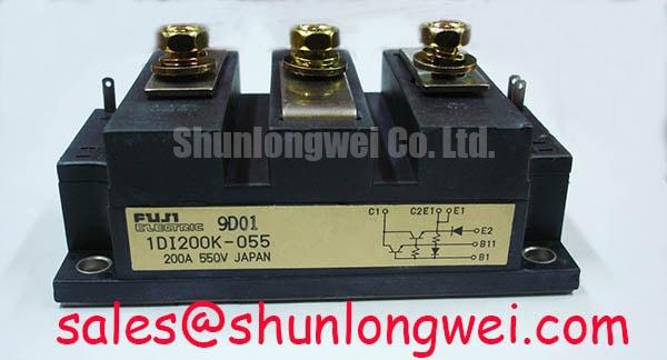
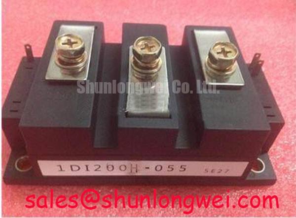
1DI200H-055 Fuji Electric 200A Power Transistor Module
When a heavy duty variable frequency AC motor drive trips during acceleration, isolate the DC link, discharge it under the drive manufacturer’s procedure, and inspect the power module before applying another test pulse. The 1DI200H-055 is a Fuji Electric bipolar power transistor module in the 200 A class. The system engineer should verify its voltage rating and current-rating conditions from the applicable datasheet and match the replacement against the original drive documentation and switching topology.
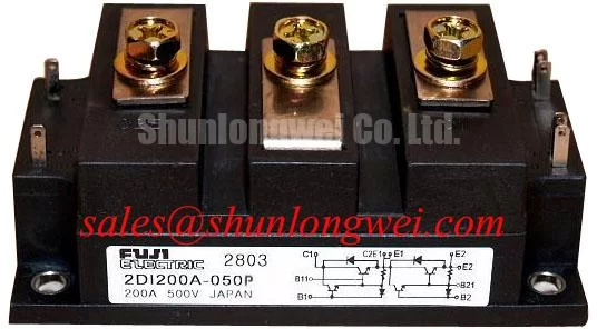
The module uses a power transistor module package for high current switching service. Before removal, record cable positions, terminal hardware, heatsink contact condition, and the base drive connection arrangement. A cold resistance comparison between the removed unit and a known good device in an equivalent circuit position can help identify an abnormal semiconductor path, but it does not replace controlled live testing. For broader topology reference, engineers evaluating the surrounding converter stage can review the Fuji Electric PIM power integrated module information. These IGBT-based products are a separate device category, not documentation for the 1DI200H-055.
Assembly Integrity and Layout Architecture for the 1DI200H-055
Thermal interface control begins with a flat, clean heatsink surface and a continuous, even layer of thermal interface material. A practical engineering recommendation is to control the applied TIM thickness within approximately 50 to 100 µm when that range is compatible with the selected compound and the heatsink flatness. This is a design consideration, not an official 1DI200H-055 factory rating. Excess compound can create hydraulic pressure during tightening, while uncovered areas increase local thermal resistance.
Check the baseplate and heatsink for burrs, contamination, raised machining marks, and visible curvature. If the mating surfaces do not settle evenly, compensate through the approved mechanical interface rather than forcing the module down with one fastener. Start each screw by hand, bring the hardware into light contact in a diagonal sequence, and then apply the equipment manufacturer’s specified torque in progressive stages. The final value must follow the terminal, screw, washer, and heatsink assembly specification; it should not be inferred from the module’s 200 A rating.
Keep the high current path short and physically separated from sensitive base drive wiring. The base drive loop should avoid parallel routing with the collector or emitter bus, while the DC link and switching commutation loop should be arranged to limit parasitic inductance. When integrating the module into a variable frequency drive cabinet, designers should verify creepage, clearance, busbar movement, and base driver reference integrity under the actual enclosure and vibration conditions. The 6DI120D-060 may be reviewed as another Fuji power module during mechanical and electrical comparison, without assuming the same internal configuration or interchangeability.
⚠️ Field Alert: Never tighten one corner fully before the remaining mounting points are seated, because uneven clamping can distort the thermal interface and stress the package.
Preventing Spurious Faults and Mechanical Leadframe Stress
Main terminal hardware must clamp the external busbar without levering against the module body. Confirm that the screw thread engagement, washer stack, busbar position, and terminal height match the original mechanical arrangement. A busbar that is pulled sideways into alignment can transfer vibration and thermal expansion forces into internal copper joints. During service inspection, look for displaced washers, witness marks around the terminal, cracked insulation, and a busbar that springs away when loosened.
Mechanical checks should be paired with switching waveform review. A fast freewheeling diode recovery event can increase voltage overshoot and radiated noise when the commutation loop contains excessive stray inductance. MOV devices, RC or RCD snubbers, and other suppression networks should be selected from measured transient behavior and the drive’s insulation coordination requirements. Their presence does not automatically establish a suitable protection level for this module. Verify the actual collector emitter transient, base emitter voltage, and common mode behavior with an appropriately rated differential probe, and check base drive current using a suitable measurement method.
For comparison with another converter module, the 6DI150A-060 can be reviewed after confirming its circuit configuration. It should not be treated as a substitute for the 1DI200H-055 without confirming circuit function, ratings, terminal geometry, and control requirements. Diode recovery and base drive supply stability also require inspection when a drive reports intermittent switching faults. If the drive uses a bootstrap-powered driver, its charging behavior must also be checked.
1DI200H-055 Circuit Protection and High Speed Fault Management
Collector emitter voltage monitoring or desaturation protection, where used, should be coordinated with the base driver, the transistor’s safe operating area, DC link impedance, and the actual switching loop. The suitable response time and threshold must be established from the driver design and the module’s applicable documentation; an IGBT short circuit withstand time should not be assumed for this bipolar transistor module. A fault present at turn on and a fault developing during conduction place different demands on detection, blanking, and energy control.
When a fault occurs, controlled turn off can help limit inductive overvoltage, but the base drive waveform and current interruption must remain within the transistor’s documented switching and safe operating area limits. The base driver must still maintain a clean reference, adequate isolation, and a controlled fault signal path. Minimize commutation loop inductance to suppress turn off overshoot, then verify peak voltage margins against the device rating at the actual drive DC link voltage during controlled switching tests. Do not rely on a fuse alone: semiconductor fuse selection must consider the complete prospective fault waveform, clearing characteristics, and coordination with the transistor’s safe operating area and electronic protection.
The DC link MOV network, snubber arrangement, fast fuse, and dead time form one protection system. Engineers should assess their interaction rather than tuning each item in isolation. Dead time must account for bipolar transistor storage and turn off behavior under the actual base drive conditions. If a bootstrap supply is used, check whether its capacitor retains sufficient charge during the intended pulse pattern and whether the charging diode recovers cleanly at the switching frequency. The Precision Gate Drive Design guide provides general context for switching-device layout and protection coordination, but gate drive requirements must not be applied directly to this base-driven transistor.
For application-specific switching limits, base drive requirements, safe operating area, and transient verification, consult the applicable 1DI200H-055 datasheet and original drive service documentation. The Fuji Electric V-Series IGBT Application Manual concerns a different device family and does not establish ratings or drive requirements for this module. The 1DI200H-055 should be released into service only after its electrical ratings, terminal arrangement, thermal interface, and protection response have been checked against the original heavy duty AC drive design.