Content last revised on July 5, 2026
An Engineer's Look at the 7MBR35SB140: Efficiency and Integration in a Compact Form
Introduction: A Strategic Overview
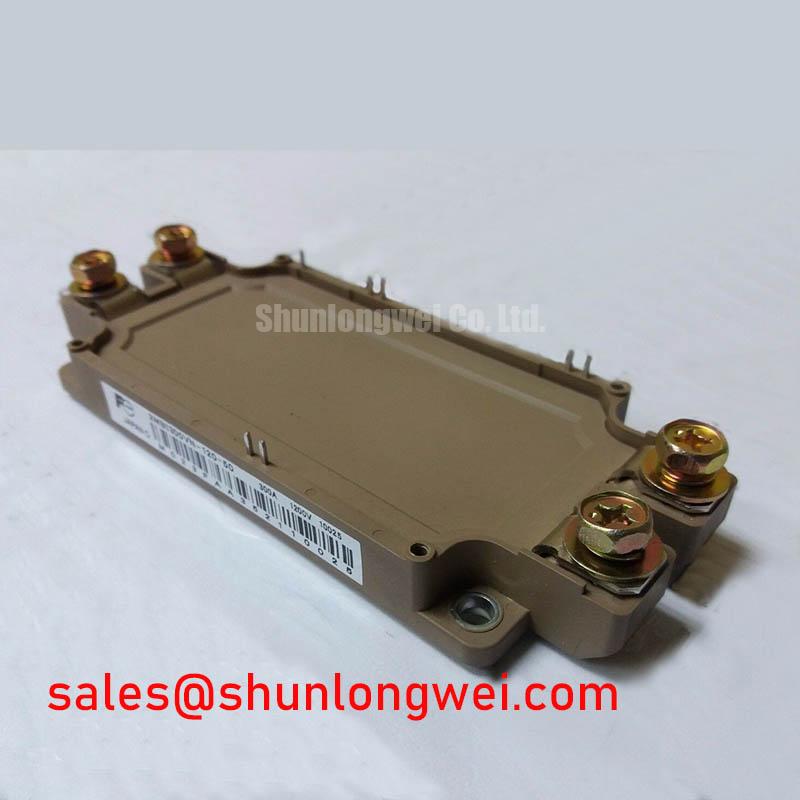
The Fuji Electric 7MBR35SB140 is a highly integrated Power Integrated Module (PIM) designed to optimize performance in low to medium-power motor drive applications. Combining a 1400V collector-emitter voltage with a 35A continuous collector current, this module provides a robust solution for engineers seeking both efficiency and design simplicity. Its key benefits include enhanced system reliability due to a higher voltage margin and a streamlined design process enabled by its 7-in-1 CIB (Converter-Inverter-Brake) topology. For systems operating on 480V or 575V AC lines, the 1400V rating offers a critical safety buffer against voltage transients, a common challenge in industrial environments. This module is the optimal choice for power conversion systems up to ~15 kW where minimizing both physical footprint and electrical losses are primary design objectives.
Application Scenarios & Value
System-Level Benefits in Compact Motor Drive Design
The 7MBR35SB140 excels in applications where space and efficiency are critical engineering constraints. Its primary value is realized in the design of compact Variable Frequency Drives (VFDs), AC and DC servo drive amplifiers, and smaller-scale Uninterruptible Power Supplies (UPS). The engineering challenge in these systems is often managing thermal dissipation and component layout within a confined enclosure. The 7MBR35SB140 directly addresses this by integrating a three-phase converter, a three-phase inverter, and a dynamic brake chopper circuit into a single, compact package.
This high level of integration offers a tangible advantage over discrete component solutions. By reducing the number of individual power devices, it simplifies PCB layout, minimizes parasitic inductance, and significantly reduces assembly time. Furthermore, its low collector-emitter saturation voltage (VCE(sat)) of 2.1V (typ) is a critical parameter. Think of VCE(sat) as the electrical "friction" the switch creates when it's on. A lower value, like that of the 7MBR35SB140, means less energy is wasted as heat during operation. This translates directly to higher overall efficiency and reduced requirements for cooling hardware, allowing for a more compact and cost-effective thermal design.
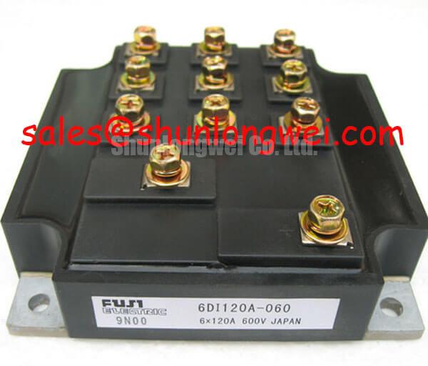
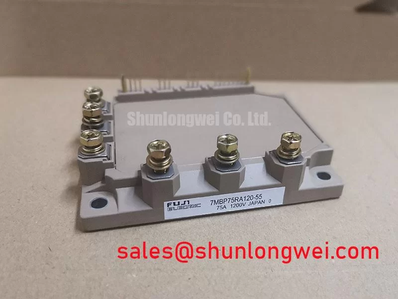
While the 7MBR35SB140 is ideal for 35A requirements, for systems demanding higher current handling in a similar integrated package, the related 7MBR50SB120 offers a 50A capability at a 1200V rating. For lower-power designs, the 7MBR25SA120-50 provides a 25A solution.
Key Parameter Overview
Decoding the Specs for Optimal Switching Performance
The performance of the 7MBR35SB140 is defined by a set of key electrical and thermal characteristics that are crucial for system design and simulation. The following table highlights the essential parameters, grouped by their function within the module.
| Parameter | Symbol | Condition | Value |
|---|---|---|---|
| Inverter Section (per IGBT) | |||
| Collector-Emitter Voltage | Vces | Tj = 25°C | 1400V |
| Continuous Collector Current | Ic | Tc = 80°C | 35A |
| Collector-Emitter Saturation Voltage | VCE(sat) | Ic = 35A, Vge = 15V | 2.1V (typ) / 2.7V (max) |
| Turn-on Switching Loss | Eon | Ic = 35A, Vcc = 600V | 4.2 mJ/pulse (typ) |
| Turn-off Switching Loss | Eoff | Ic = 35A, Vcc = 600V | 4.8 mJ/pulse (typ) |
| Brake Section (Chopper IGBT) | |||
| Collector-Emitter Voltage | Vces | Tj = 25°C | 1400V |
| Continuous Collector Current | Ic | Tc = 80°C | 35A |
| Thermal and Mechanical | |||
| Max Junction Temperature | Tj max | - | 150°C |
| Mounting Torque | - | M5 Screws | 2.5 - 3.5 Nm |
This data is for reference only. For detailed specifications and performance curves, please download the official datasheet.
Download the 7MBR35SB140 datasheet for detailed specifications and performance curves.
Technical Deep Dive
Analyzing Conduction and Switching Losses for Enhanced Efficiency
A primary goal in power electronics design is the minimization of energy losses, which manifest as heat. The 7MBR35SB140 is engineered with this in mind, and understanding its loss characteristics is key to maximizing system efficiency. The two dominant loss mechanisms in an IGBT Module are conduction losses and switching losses.
Conduction losses occur when the IGBT is in the "on" state and are primarily determined by the VCE(sat). With a typical VCE(sat) of 2.1V at its nominal current, the 7MBR35SB140 demonstrates Fuji Electric's focus on reducing on-state resistance. This directly impacts the thermal load on the heatsink, a critical aspect of Thermal Management. A lower conduction loss allows engineers to either push for higher power density or improve system reliability by operating at a lower junction temperature.
Switching losses, defined by Eon (turn-on energy) and Eoff (turn-off energy), occur during the transition between the on and off states. These losses are frequency-dependent; the higher the PWM frequency, the more significant they become. The specified typical values of 4.2 mJ (Eon) and 4.8 mJ (Eoff) provide the data needed for accurate loss calculations, enabling designers to select an optimal switching frequency that balances efficiency against other factors like acoustic noise and motor performance. The inclusion of an integrated thermistor further supports this optimization by providing real-time temperature feedback to the control system, allowing for dynamic adjustments to prevent thermal runaway.
Frequently Asked Questions (FAQ)
How does the 1400V Vces rating of the 7MBR35SB140 benefit a design for a 480V AC system?
A standard 1200V IGBT provides sufficient blocking voltage for a 480V AC line under ideal conditions. However, industrial power grids are prone to transient overvoltages from events like lightning strikes or switching of large inductive loads. The 1400V rating of the 7MBR35SB140 provides a significantly larger safety margin. This enhanced headroom reduces the stress on the device during voltage spikes, directly improving the long-term reliability and robustness of the end application, such as a Variable Frequency Drive (VFD).
What is the primary advantage of the integrated 7-in-1 CIB configuration?
The main advantage is system simplification. By combining the input rectifier, brake chopper, and output inverter into one module, it reduces the bill of materials (BOM), shrinks the required PCB area, and simplifies the manufacturing process. This integration also minimizes parasitic inductance between stages, which can improve electrical performance and reduce voltage overshoot, contributing to a more reliable and compact final product.
For further inquiries or to discuss your specific design requirements for the 7MBR35SB140, please contact our technical support team for assistance.