Content last revised on September 1, 2026
Thermal Interface Material (TIM) Thickness Uniformity and Void Minimization
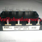
During emergency floor repairs on precision stepper and brushless DC (BLDC) servo actuators, power module failure often traces directly back to mechanical assembly defects rather than silicon anomalies. The 6MBP30RTB060 by Fuji Electric is an integrated intelligent power module rated at VCES = 600V and a continuous inverter collector current of IC = 30A at a case temperature of 80°C (Official Datasheet Specification). Because its internal power stages deliver compact switching density within motion control architectures, the thermal pathway between the copper baseplate and the extruded aluminum heat sink serves as the primary barrier against catastrophic thermal runaway.
The module exhibits a rated junction-to-case thermal resistance of Rth(j-c) = 2.5 °C/W per IGBT in the inverter portion (Official Datasheet Specification). When conducting field replacement, technicians frequently introduce uneven grease layers. A layer of thermal interface material (TIM) that exceeds 100 μm degrades thermal transfer because the bulk thermal conductivity of standard zinc-oxide or silicone-based paste (typically 1.0 to 3.5 W/m·K) is significantly lower than metallic copper (approximately 390 W/m·K). Conversely, applying less than 50 μm risks leaving microscopic air pockets across the baseplate concavity, creating dry zones where local thermal impedance spikes.
⚠️ Field Alert: Never use a finger, cardboard scrap, or manual wiping to spread TIM across the baseplate of the 6MBP30RTB060. Manual application introduces air voids and variable grease ridges. Always utilize a laser-cut metal stencil or a fine notched squeegee designed to deliver a uniform wet-film thickness between 60 μm and 80 μm (Design Consideration). A visual check showing grease pooling around the outer mounting tabs while the center remains dry indicates excessive baseplate crowning or an uneven heat sink surface.
Achieving proper contact pressure requires strict adherence to sequential mounting torques. Heatsink flatness across the mounting area must remain within 50 μm per 100 mm run, with a surface roughness of Rz ≤ 10 μm (General Industry Design Consideration). Fasten the module using two-point M4 screws:
- Apply an initial pre-tightening torque of 0.5 N·m to screw 1, followed by 0.5 N·m to screw 2 to seat the module uniformly into the thermal grease layer.
- Allow 15 to 30 minutes for the viscous matrix of the TIM to relax and displace outward from high-pressure contact zones.
- Apply the final operational torque of 1.3 to 1.7 N·m alternately across both fasteners (Design Consideration based on M4 screw torque into tapped aluminum).
Failure to follow this two-stage torquing sequence tilts the internal ceramic substrate, introducing mechanical sheer stresses that can crack internal direct-bonded copper (DBC) layers under cyclic thermal expansion.
Evaluating Thermal Capacitance vs Heat Sink Time Constant under Surge Bursts
Precision servo drives execute rapid forward-reverse reversals, dynamic braking, and instantaneous torque boosting during motor lockup or acceleration ramps. In these duty cycles, junction temperatures fluctuate dynamically long before the heat sink mass reaches steady-state equilibrium. The 6MBP30RTB060 exhibits a collector-emitter saturation voltage of VCE(sat) = 2.2V typical and 2.7V maximum under rated 30A current (Official Datasheet Specification). Under a sudden current overload during axis positioning, the instantaneous power dissipation concentrated on the silicon dice surges within milliseconds.
Silicon dies exhibit a very small thermal capacitance, characterized by thermal time constants in the range of 1 to 10 milliseconds, whereas industrial aluminum extrusions possess thermal time constants extending from 50 to 300 seconds. Consequently, during high-torque bursts lasting 100 to 500 ms, the bulk heat sink remains virtually at its initial ambient temperature, while the active silicon junction temperature undergoes a steep rise governed primarily by the module internal layers (die solder, copper slug, DBC substrate, and baseplate solder). Transient thermal impedance curves must be evaluated to ensure that junction temperatures remain safely below the absolute maximum threshold during peak holding torque.
| Operating Parameter | Specification / Rating | Engineering Significance in Servo Loops |
|---|---|---|
| Collector-Emitter Voltage (VCES) | 600V (Official Datasheet Specification) | Operating headroom for 200–240V AC rectified utility buses |
| Inverter Collector Current (IC) | 30A at TC = 80°C (Official Datasheet Specification) | Continuous rated drive capacity for BLDC/stepper motors |
| Saturation Voltage (VCE(sat)) | 2.2V Typ / 2.7V Max (Official Datasheet Specification) | Direct driver of conduction losses and internal heat generation |
| Thermal Resistance (Rth(j-c)) | 2.5 °C/W per IGBT (Official Datasheet Specification) | Defines steady-state thermal conductivity from junction to base |
| Internal NTC Resistance (R25) | 50 kΩ ±5% at 25°C (Official Datasheet Specification) | Linear tracking for active over-temperature cut-off logic |
For high-inertia industrial actuators where acceleration profiles push thermal dissipation beyond the 30A continuous rating of the 6MBP30RTB060, engineers often specify higher-capacity dual-pack topologies such as the 2MBI150-060 to achieve adequate transient thermal margin. The integrated NTC thermistor inside the 6MBP30RTB060 provides a baseline resistance of 50 kΩ at 25°C (Official Datasheet Specification). Because the thermistor is mounted onto the DBC substrate rather than the silicon surface, field engineers must incorporate a response delay into their firmware trip settings; the thermistor output typically lags silicon junction excursion spikes by several hundred milliseconds.
To stabilize intermediate DC link voltages and absorb low-frequency ripple during high-duty acceleration phases, precision servo drives rely on Nichicon Inverter Grade Aluminum Electrolytic Capacitors. Comprehensive verification workflows for diagnosing power component burnout, gate leakage, and dielectric degradation can be referenced in the Field Engineer’s Handbook.
Kelvin Emitter Connection & Parasitic Inductance Minimization in High-Speed Switching
Operating a BLDC servo drive at carrier frequencies between 10 kHz and 20 kHz delivers smooth motion and minimizes acoustic motor whine, but steep switching speeds amplify mutual trace coupling. Within the internal architecture of the 6MBP30RTB060, dedicated driver ICs interface with the IGBT gates. However, external PCB layout errors frequently compromise gate stability by coupling high-current inverter return paths into the low-level signal reference.
When current commutates rapidly through an IGBT, parasitic inductance in the emitter path creates an induced voltage across that parasitic element. If the gate driver reference shares this high-current path, this induced voltage acts as negative feedback, directly counteracting the gate turn-on command and slowing down switching transitions. Worse, during hard turn-off, the rapid current drop induces a positive counter-voltage that can momentarily elevate the gate above its threshold voltage, resulting in dangerous high-frequency parasitic oscillations or direct shoot-through across the DC rail.
Implementing a dedicated Kelvin emitter connection isolates the auxiliary gate-drive reference from the power emitter conductor. The gate drive charging and discharging loop must circulate exclusively through the auxiliary emitter terminal directly to the dedicated gate driver ground pin. Ensure that the gate forward trace and its Kelvin emitter return trace are routed as an unshielded, closely coupled differential pair or overlaid on adjacent PCB layers to cancel magnetic loop pickup. In high-frequency servo drives, steep voltage transitions (high du/dt) can stress motor phase windings; implementing a properly calculated LC Filter Design for Inverter Output Sine Wave Shaping suppresses high-frequency transmission line reflections at long motor cable runs.
Planar Symmetrical Busbar Geometry: Achieving L_sigma < 20nH to Protect Silicon Junctions
The 6MBP30RTB060 operates on three-phase or single-phase 200V to 240V utility grids, where the nominal DC link voltage settles between 280V and 380V DC. Because the absolute maximum collector-emitter rating is VCES = 600V (Official Datasheet Specification), the remaining safety headroom is roughly 220V. When an axis motor experiences a line-to-ground fault or rapid short-circuit desaturation, local current rates of change can exceed 1200 A/μs during turn-off.
Under these high di/dt switching conditions, total parasitic loop inductance across the DC bus creates an overvoltage spike that adds directly to the continuous DC link voltage. If the stray inductance exceeds 35 nH, this peak transient voltage can easily breach the 600V silicon junction breakdown limit, puncturing the collector-emitter barrier. Achieving a low stray inductance (Lσ < 20 nH) demands planar laminated busbar geometry across the high-voltage connections.
Technicians and hardware designers should route positive and negative bus conductors using parallel, wide copper plates separated by thin dielectric films (such as 0.25 mm to 0.5 mm Nomex or Kapton sheet). The counter-flowing currents establish opposing magnetic fields that cancel mutual inductance throughout the power bridge. Connect low-inductance polypropylene film snubber capacitors (0.1 μF to 0.47 μF, rated for 630V DC minimum) directly across the P and N terminal pins of the module, keeping lead lengths below 5 mm (Design Consideration).
For auxiliary circuits, dynamic braking arms, or primary rectification interfaces operating on shared DC rails alongside the 6MBP30RTB060, engineers utilize dedicated single-switch or half-bridge modules like the 1MBI200NH-060. Using calibrated dual-trace oscilloscopes equipped with isolated differential probes directly on the power pins enables field technicians to confirm that the voltage overshoot never exceeds 540V peak under maximum acceleration and braking cycles, maintaining a reliable 10% derating margin beneath the official 600V rating.