
Content last revised on October 14, 2026
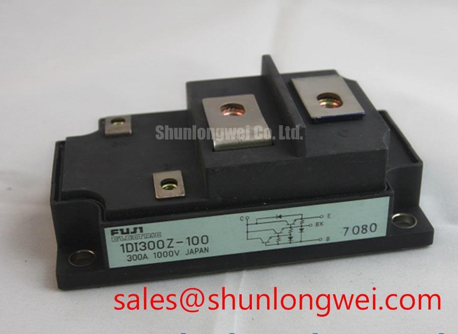
1DI300Z-100 Incoming Inspection and Product Identification
- Isolate the equipment, discharge the DC link, and confirm the absence of voltage before disconnecting the 1DI300Z-100 power terminals.
- Match terminal markings to the circuit drawing before recording cold-state resistance and diode-mode readings in both polarities.
- Inspect the mounting surface, terminal hardware, and thermal interface for damage or uneven contact.
- Separate the driver connections from the power circuit before evaluating control-terminal impedance or insulation test requirements.
The Fuji Electric 1DI300Z-100 is a Power Transistor / Darlington Module. Incoming inspection should distinguish its transistor control interface from an IGBT gate interface: driver compatibility cannot be established from the package appearance or current rating alone. Record measurements with terminal polarity, instrument mode, and module temperature so comparisons remain repeatable.
| Product characteristic | Specification |
|---|---|
| Model | 1DI300Z-100 |
| Manufacturer | Fuji Electric |
| Transistor blocking-voltage rating | Verify the applicable rating and conditions in the manufacturer’s datasheet; do not substitute an insulation withstand-voltage rating. |
| Specified rated current | 300 A, subject to the datasheet conditions |
| Package | Power Transistor Module |
| Rating definitions, terminal diagram, and test conditions | Consult datasheet |
💡 Bench Tip: Keep the control terminals under appropriate ESD protection and compare cold-state readings with a documented known-good module under matching test conditions.
Assembly Integrity & Layout Architecture: Planar Symmetrical Busbar Geometry for 1DI300Z-100
Trace the commutation loop through the module terminals, DC-link connections, and return conductor before evaluating busbar symmetry. As a Design Consideration, closely coupled outgoing and return paths can reduce stray inductance, but terminal access, mechanical loading, and electrical clearances must remain compatible with the equipment design.
An Engineering Calculation relates switching overshoot to the DC-link voltage plus stray inductance multiplied by the current-change rate. This relationship explains why a long return path can increase turn-off stress; it does not establish a module-specific inductance target. Measure the switching waveform with suitable probes and compare the peak against the applicable transistor blocking rating, rather than treating an unspecified voltage definition as a switching limit.
For replacement assessment, compare 1DI300D-100 with the original module across terminal assignments, control requirements, electrical ratings, and mounting geometry. A related designation alone does not establish direct interchangeability. Check that altered conductor routing will not impose bending loads on the terminals.
Assembly Integrity & Layout Architecture: Isolated DC-DC Power Supply Sizing for 1DI300Z-100
Size an isolated driver supply around the actual transistor drive circuit, including its sustained control-current demand and switching behavior. A Darlington interface requires a different assessment from the predominantly capacitive gate load of an IGBT. Fuji Electric’s High-Speed Discrete IGBT information concerns a separate device family and should not be used as the terminal or drive specification for this module.
Design Consideration: evaluate the supply’s isolation classification and transient immunity against the equipment working voltage and measured common-mode disturbances. Inspect the complete barrier, including connectors and board spacing. A withstand-voltage value alone does not establish reinforced insulation or long-term insulation reliability; partial discharge describes a distinct insulation phenomenon, not a qualification result for the 1DI300Z-100.
Where the equipment uses parallel modules, compare on-state characteristics under matching current and thermal conditions. Do not assume a favorable saturation-voltage temperature coefficient. Symmetrical conductors help control path differences, while driver balance and thermal contact require separate evaluation.
Benchtop Waveform Tuning: Mitigating Commutation Turn-Off Voltage Spikes on 1DI300Z-100
Locate the freewheeling path on the equipment schematic before interpreting diode-mode readings or commutation waveforms. A meter reading across installed power terminals can include parallel circuitry; isolate the relevant path before attributing the result to the module. Record polarity and compare against the documented circuit configuration without assigning an invented forward-voltage acceptance window.
Design Consideration: diode reverse recovery can influence current peaks, ringing, and transistor switching stress. Examine the actual diode current and transistor voltage together to distinguish recovery behavior from probe artifacts or conductor resonance. Evaluate snubber changes through measured peak stress, damping, and dissipation rather than selecting capacitance from the current rating alone.
For this transistor module, review base-drive shaping and turn-off behavior instead of prescribing an IGBT gate resistor. When investigating service-related changes, the Field Engineer’s Handbook provides broader testing context; retain equipment-specific waveforms and thermal observations as the acceptance record rather than inferring a lifetime from a static bench test.
1DI300Z-100 Thermal-Electrical Optimization: Braking Resistor Sizing and Chopper Tuning
Identify the braking branch and its switching device before assessing whether the 1DI300Z-100 belongs in that circuit. Trace the resistor connection, driver output, and protection feedback; neither an internal braking function nor an IGBT chopper structure should be assumed from the module designation.
Design Consideration: braking-resistor evaluation depends on deceleration energy, repetition rate, allowable DC-link rise, and resistor thermal capability. Assess the switching device against its operating envelope and measured losses, with mounting contact and cooling checked under representative duty. If the assembly also contains a 6MBI300U-170, evaluate that module as a separate subsystem component, not as a drop-in substitute or an assumed rectifier.
Engineers evaluating high-speed rail or heavy-freight locomotive traction-inverter repairs should establish compatibility from the original equipment design. During controlled braking tests, correlate DC-link behavior with chopper commands and resistor temperature, then investigate deviations in sensing, drive timing, cooling, or the load path before assigning the fault to the transistor module.