

Content last revised on October 15, 2026
1DI300ZP-120 Circuit Protection & Reliability: Calibrating High-Frequency Common-Mode Bearing Current
- Isolate the power supply, verify DC-link discharge, and disconnect the 1DI300ZP-120 before comparing cold terminal resistance with the equipment service reference.
- Match the terminal markings and base-drive connections to the original circuit diagram before reconnecting the power stage.
- Inspect the mounting surface, terminal hardware, and heatsink contact area for contamination, distortion, or loose connections.
- Check the protection circuit and discharge path before attempting a controlled restart.
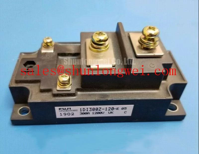
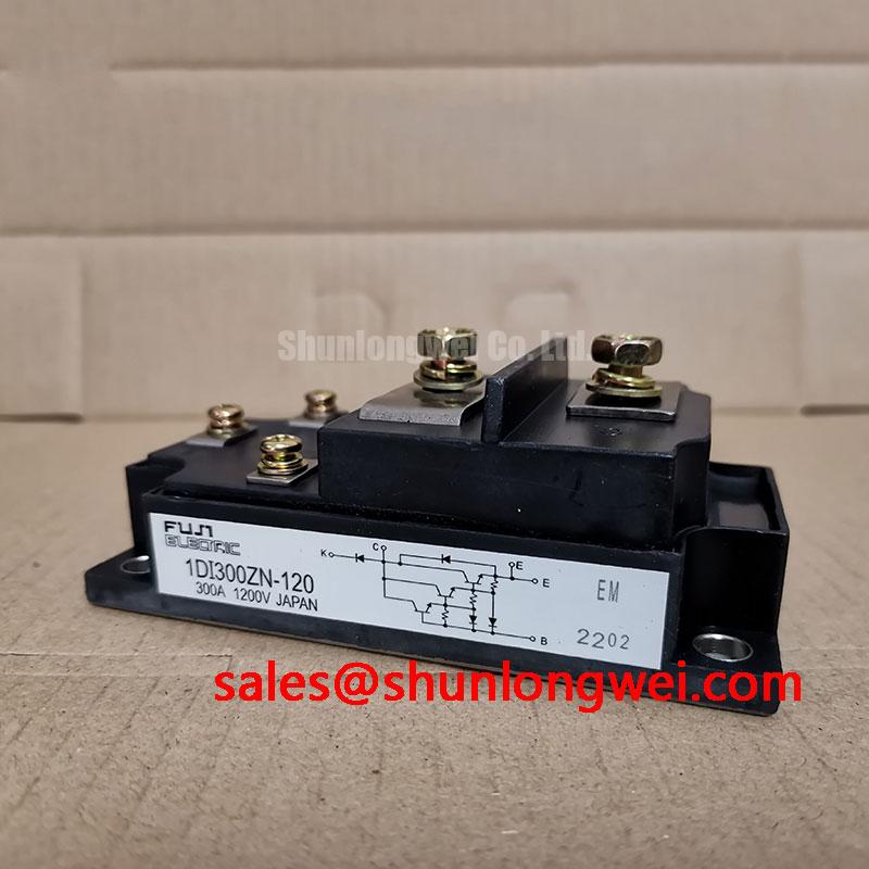
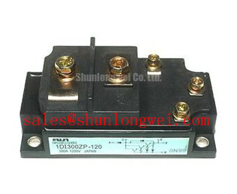
The Fuji Electric 1DI300ZP-120 is a Power Transistor / Darlington Module with supplied specification values of 1200 V rated voltage and 300 A rated current, housed in a Power Transistor Module package. Terminal assignments, rating conditions, switching characteristics, and mounting limits require the model-specific datasheet. Its bipolar drive requirements are central to replacement assessment; an IGBT gate-driver arrangement does not establish compatibility.
Measure switching transients at the converter output and motor terminals separately when assessing a motor-connected installation. As a Design Consideration, cable reflections can produce motor-terminal peaks approaching twice the incident voltage step under strongly mismatched termination conditions. That motor-terminal waveform must be distinguished from collector-emitter overshoot measured directly across the module.
Use appropriately rated differential measurement equipment and examine the existing cable routing, shield termination, and protective bonding. Common-mode bearing current follows capacitive coupling and return-path impedance; a reflected differential voltage peak alone does not establish its cause. Compare shaft-voltage behavior and common-mode current with the equipment maintenance reference before changing filtering.
As an Engineering Recommendation, evaluate an output reactor or dv/dt filter against cable characteristics, switching conditions, load current, and filter heating. Preserve the equipment’s specified electrical clearances and determine component sizing through system measurements. Fuji Electric’s Power Semiconductor & IPM Modules resource provides broader product-family context; it does not establish IGBT switching behavior for this Darlington module.
1DI300ZP-120 Operational Boundaries: Evaluating Short-Circuit Energy Let-Through Matching Limits
Compare the semiconductor fuse’s total clearing I²t at the actual circuit voltage and prospective fault current with documented withstand information for the protected current path. As a Design Consideration, fuse coordination also depends on circuit inductance, interruption behavior, and protection response. Fuse I²t alone cannot guarantee that a transistor survives a short circuit or that its enclosure remains intact.
Assess the Darlington transistor against its documented safe operating area and base-drive shutdown behavior. Any diode surge-current rating, including ITSM, applies only to the specified diode and test conditions; it cannot be transferred to the transistor. After a protection event, investigate the drive circuit, current sensing, and cooling path before restarting.
Parallel operation requires measured current sharing across the intended operating range. Do not assume a positive on-state voltage temperature coefficient for this bipolar device. Symmetrical conductors, comparable thermal contact, and coordinated base drive are Design Considerations. When evaluating 1DI300A-120, compare terminal geometry, drive demand, switching behavior, and safe operating area before accepting interchangeability.
1DI300ZP-120 Circuit Protection & Reliability: Preventing Ceramic Substrate Rupture
Inspect the module mounting face and heatsink for burrs, contamination, and uneven contact before tightening the fasteners. Establish acceptable flatness and any permitted baseplate curvature from the applicable mechanical drawing; visual appearance alone cannot establish mounting conformity or internal substrate condition.
As an Engineering Recommendation, apply the specified thermal interface material evenly and tighten mounting fasteners progressively in a diagonal sequence when the assembly instructions permit. Bond-line thickness and final torque depend on the module instructions, interface material, and mounting hardware. A generic grease thickness or bolt torque should not become an acceptance limit for this part.
Field Alert: Never pull an uneven module-to-heatsink joint flat by increasing bolt torque beyond the applicable mounting specification. After assembly, assess contact quality through the approved thermal inspection method and compare temperature behavior under equivalent load and cooling conditions.
Assembly Integrity & Layout Architecture: Implementing Thermal Cycling Margins of Internal Braking for 1DI300ZP-120
Trace the braking branch on the equipment schematic before assigning any braking function to the replacement module. As a Design Consideration, a regenerative system needs a defined energy destination, with the braking switch and resistor assessed against deceleration energy, repetition rate, cooling, and protection settings. The module designation does not establish an integrated braking circuit.
Keep braking-current paths and drive connections arranged to limit unwanted coupling, while maintaining specified clearances around hot resistor assemblies. The 1DI400MN-120 can be considered in a complementary power-stage assessment only after establishing its circuit role. Fuji Electric’s PIM 7-Pack information describes a separate integrated topology, rather than this module’s internal circuit.
Compatibility assessment for an industrial inverter welder or medium-frequency induction-heating supply should address base drive, switching losses, and cooling. As an Engineering Recommendation, evaluate repeated thermal excursions across the actual duty cycle rather than assigning an unsupported service-life figure. The Ultimate IGBT Knowledge Base offers comparative switching-device background; Darlington-specific acceptance limits remain tied to this device’s characteristics.