Content last revised on October 3, 2026
1DI300ZP-120-02 Thermal and Electrical Checks: Establishing a Reliable Baseline
With the DC link discharged, compare the cold terminal readings of the 1DI300ZP-120-02 against the equipment schematic and a documented known-good unit before connecting a test supply. Identify each terminal from the original Fuji Electric documentation rather than from its position on the housing alone. A meter reading can reveal an open path or an apparent short, but it cannot establish the module’s full operating condition.
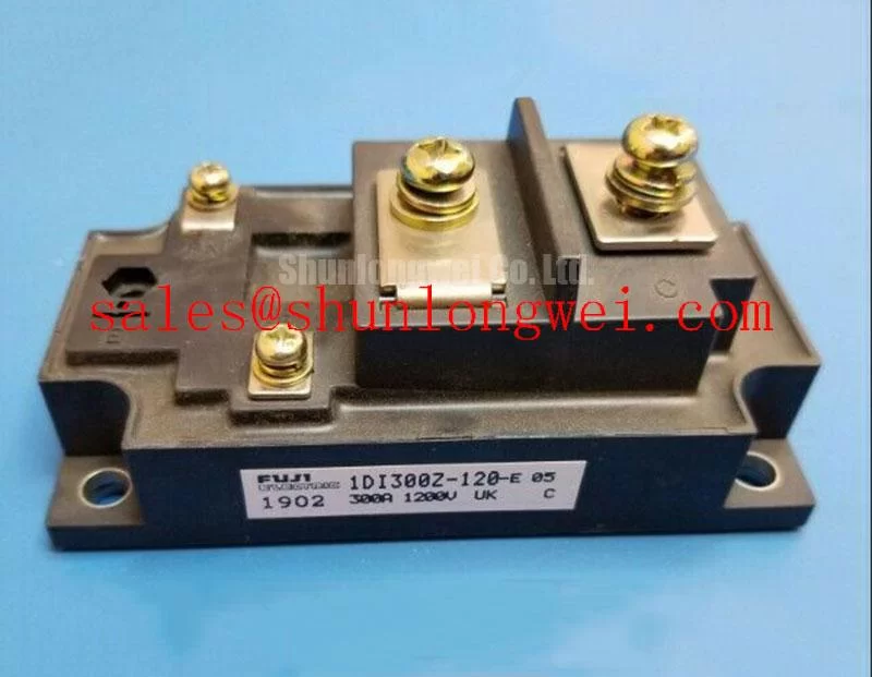
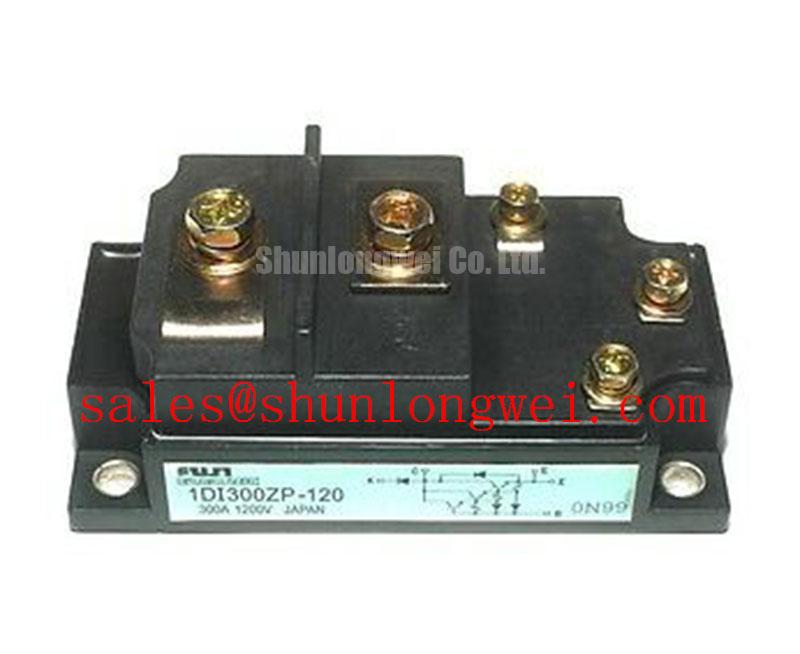
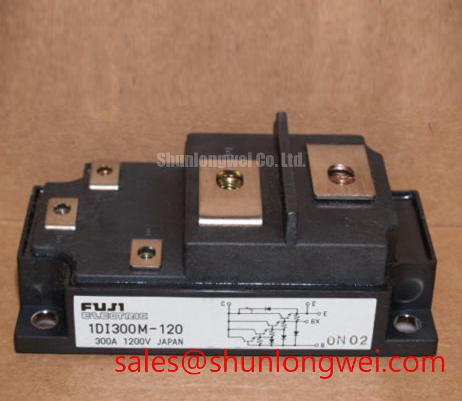
The Fuji Electric 1DI300ZP-120-02 is a Power Transistor Module with a stated voltage rating of 1200 V and current rating of 300 A, each an Official Specification supplied for this model. Those ratings are useful first checks when evaluating a repair, but they do not establish terminal compatibility, drive requirements, cooling capacity, or suitability for a particular switching duty. The original part documentation and the equipment circuit drawing remain necessary for those decisions.
Start incoming inspection with the interfaces a technician can actually verify. Record the housing condition, terminal markings, mounting surfaces, and any signs of damage around the connections. With the module isolated, check terminal continuity and polarity against the documented circuit. A diode-mode reading, where the documented terminal arrangement makes that test meaningful, should be recorded with meter lead orientation and meter type; an isolated forward-voltage number has little diagnostic value without a comparable baseline.
Temperature changes the electrical behavior of power transistors, so a cold bench comparison should be performed under consistent conditions. Design Consideration: do not assume that this model has a positive on-state voltage temperature coefficient, or that parallel devices will share current naturally. Neither characteristic follows from the stated 1200 V and 300 A ratings. If the equipment uses parallel power paths, its designer should assess sharing from the applicable device documentation and measurements at the intended operating temperatures.
Before judging a module by its heat-sink temperature, inspect the installation it depends on. Check that the mounting face seats evenly, that the heat sink is clean, and that the equipment’s specified mounting procedure has been followed. Contact quality, cooling airflow, operating current, and switching pattern all affect temperature. A warm case by itself does not distinguish an electrical fault from inadequate heat removal. For a repeatable comparison, log the load condition and the temperature measurement location along with the reading.
Insulation checks require similar discipline. The 1200 V device rating is not an insulation test voltage for an assembled machine. Design Consideration: verify the relevant insulation boundaries, test method, and permissible test stress from the original module and equipment documentation before applying a high-voltage tester. Disconnect or protect connected control electronics as the equipment procedure requires; an unexplained bench withstand result should not be treated as proof of long-term insulation reliability.
Preventing Spurious Faults: Checking the Drive and Current-Return Paths
Trace the drive circuit from the controller to the module terminals before assigning a fault to the power device. Confirm terminal identities from the original pinout, then inspect connectors, solder joints, cable routing, and the return path used by the drive. High-current conductors can disturb nearby control wiring through shared impedance or coupling. Design Consideration: keeping the drive loop compact and its return path distinct from the main current route can reduce that disturbance, but the actual wiring must follow the documented terminal arrangement. A dedicated Kelvin emitter connection must not be assumed for this model.
The same boundary applies to protection functions. Desaturation detection, gate-drive timing, and staged soft turn-off are features of particular switch-and-driver implementations, not specifications established for the 1DI300ZP-120-02 by its voltage and current ratings. Confirm the device technology and control-terminal requirements in Fuji Electric’s original documentation before assessing a driver circuit. An unverified protection delay or drive setting should not be carried over from a different module.
When a controller reports an intermittent power-stage fault, capture the drive command, the relevant control-terminal waveform, DC-link behavior, and the fault signal during a controlled test permitted by the equipment procedure. Compare the sequence with a documented healthy channel where one is available. A disturbance appearing at the control terminals may originate in wiring, the driver, sensing, or the power stage; the waveform sequence helps narrow the fault without turning one symptom into a single assumed cause.
Topology matters during this review. A DC-link or auxiliary supply fault can alter what the power stage sees even when the module passes a cold check. The 6MBP100TEA060-50 is a separate component to evaluate only where the equipment schematic calls for its function; its listing does not establish a direct electrical pairing with this module. For background on how a buck–boost stage changes its output relative to its input, the buck–boost converter topology reference is useful, while the machine schematic determines which topology is actually present.
1DI300ZP-120-02 Operational Boundaries: Assessing Pulsed Thermal Loading
The 300 A Official Specification is a rating, not permission to treat every pulse or continuous operating point as thermally equivalent. To assess a repeated traction or converter load, obtain the original rating conditions and any published thermal-impedance data for this exact model. Without those data, a peak junction-temperature margin cannot be calculated responsibly from the nameplate current or a case-temperature reading alone.
Engineering Recommendation: separate a steady heating problem from a short-duration event in the test record. Capture current waveform, DC-link voltage, switching duty, case temperature, and cooling conditions under an approved operating test. If the applicable documentation provides transient thermal impedance, the equipment engineer can combine that model with measured loss and pulse history to assess junction temperature. A thermal model taken from another package or switch technology is not a substitute for model-specific data.
For a module being evaluated for an electric forklift or warehouse material-handling traction controller, begin with the installed part number and circuit topology. A vehicle’s battery voltage alone does not determine whether a 1200 V module belongs in its power stage. Verify the switching-device arrangement, drive compatibility, mechanical footprint, cooling interface, and protection scheme before considering the 1DI300ZP-120-02 for that equipment.
That approach also keeps cross-references in their proper role. The 6MBI300U-120 is a comparison candidate for a documented selection review, not an established drop-in replacement. Its circuit configuration, terminals, drive method, thermal behavior, and mounting details must be checked independently. Matching headline voltage and current figures, even where available, would not settle those questions.
Field Diagnostics and Commissioning: Confirming the Control Method Before Applying Drive
Do not apply an IGBT gate-drive procedure to the 1DI300ZP-120-02 solely because it is installed in a high-power switching assembly. The product category supplied for this part is Power Transistor Module; the stated specifications do not confirm an IGBT gate, a Miller-clamp connection, or a permissible negative gate-bias range. First identify the device’s control terminals and required drive behavior from its original documentation and the equipment schematic.
On the bench, keep the record practical: note the lead placement used for each cold terminal check, compare readings at a similar temperature, and investigate a difference before energizing the assembly. 💡 Bench Tip: Keep the module and test instruments under appropriate ESD controls while establishing the cold baseline. If a reading changes when a connector is moved, inspect that connection and repeat the measurement before attributing the change to the semiconductor.
During commissioning, watch for unintended switching commands or voltage disturbances at the documented control terminals while measuring the main power path with appropriately rated instruments. Design Consideration: minimizing coupling between control wiring and fast-changing power conductors helps make those observations interpretable; the equipment designer should verify the final routing and protection behavior under its actual switching conditions. For context on a different switch technology, The 1200 V CoolSiC™ MOSFET Advantage in Three-Phase Power Conversion discusses three-phase conversion, but it does not define drive settings for this Fuji Electric transistor module.
If the equipment uses vector control, distinguish controller calculations from device-level evidence. The direct-quadrature-zero transformation describes a control-system method; an abnormal calculated current can still require checks of current sensing, wiring, the driver, and the power module. Commissioning is complete only when the measured switching behavior and protection response agree with the machine documentation under the tested conditions.