

Content last revised on September 10, 2026
1DI300ZN-120 Inspection and Identification
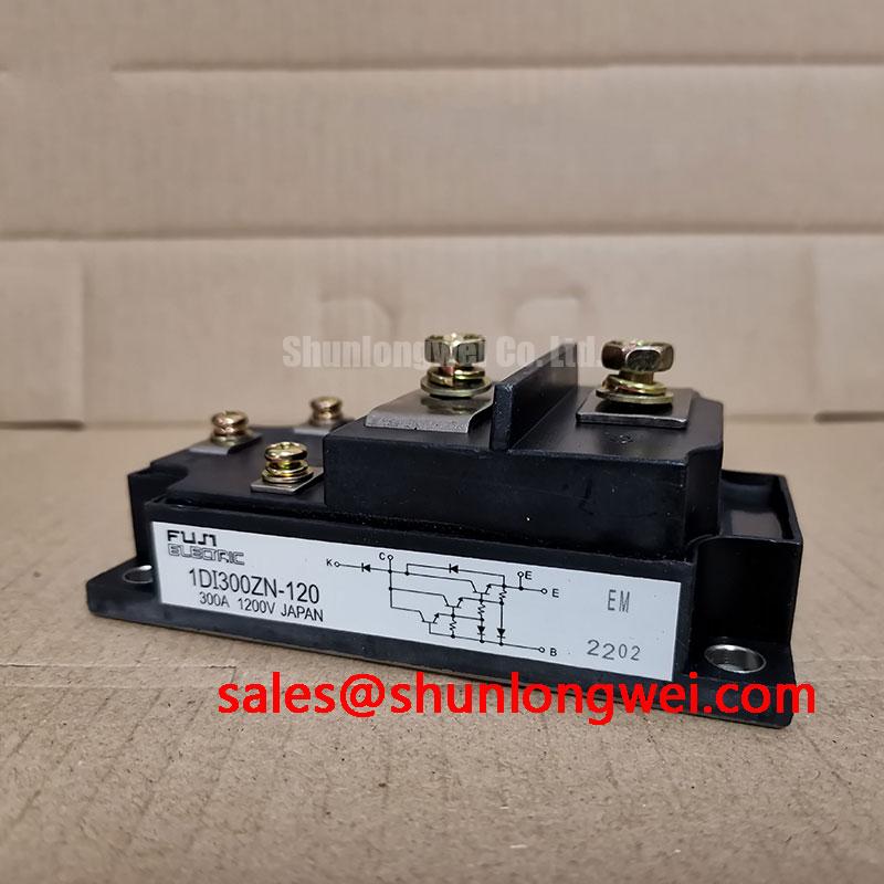
Begin incoming inspection by confirming the enclosure marking against the purchase record, then isolate the 1DI300ZN-120 from the surrounding circuit before any resistance or diode-mode measurement. This Fuji Electric power transistor module is officially rated at 1200V and 300A, with the manufacturer-listed package category of Power Transistor Module. Those ratings define the device identity, but they do not replace verification of the original equipment terminal map, control circuit, clamp network, and cooling arrangement.
| Parameter | Official Specification |
|---|---|
| Manufacturer | Fuji Electric |
| Part number | 1DI300ZN-120 |
| Voltage rating | 1200V |
| Current rating | 300A |
| Package category | Power Transistor Module |
For bench comparison, record terminal-to-terminal readings with the same meter range and probe polarity used on a known-good assembly. A diode-mode result can help reveal an unexpected low-resistance path, but it should not be treated as a standalone pass or fail value because the measured path depends on the module topology and the external circuit remaining connected. 💡 Bench Tip: Discharge the DC link, use ESD-controlled handling, and compare cold-state readings only after verifying that parallel capacitors, snubbers, and driver connections are isolated.
Benchtop Waveform Tuning: Mitigating Stress via Control-Reference Return Trace Separation on 1DI300ZN-120
The supplied official core specifications identify voltage, current, and package category, but do not establish an auxiliary-emitter terminal assignment or a gate-drive interface. Engineers should therefore verify the exact terminal legend and original Fuji Electric documentation before applying any layout practice intended for an IGBT module. A Darlington control path must not be treated as an IGBT gate connection simply because both devices appear in high-power switching equipment.
Where the original converter documentation confirms separate control and power-return paths, a Design Consideration is to keep the control-reference path away from the shared high-current return path. Mutual inductance in a shared return can alter the effective control signal during current transitions and can show up as ringing, inconsistent turn-off behavior, or unexplained stress on the control stage. Inspect the existing copper routing, terminal hardware, and driver reference point before changing any lead arrangement.
Use a differential probe to observe the relevant control terminals and the main power terminals during a controlled commissioning run. The useful comparison is between the waveform at the driver output and the waveform actually reaching the module terminals. If the traces differ significantly, investigate return-path coupling, probe grounding practice, loose hardware, and the condition of the suppression network. Fuji Electric’s power semiconductor module information provides useful manufacturer context when reviewing device-family integration requirements.
Field Diagnostics & Commissioning: Isolated DC-DC Power Supply Sizing for 1DI300ZN-120 Topologies
Before energizing an industrial inverter welder or a medium-frequency induction-heating supply, identify whether the control circuit uses an isolated supply, a bootstrap arrangement, or another driver architecture. The official specifications provided for the 1DI300ZN-120 do not state isolation voltage, common-mode transient immunity, switching-frequency capability, or driver supply requirements. These properties must be verified from the original equipment documentation and the selected driver data sheet rather than inferred from the module’s 1200V and 300A ratings.
As a Design Consideration, galvanic isolation and transient behavior should be evaluated at the complete driver and power-stage level. Spurious control pulses can originate from inadequate isolation performance, poor return routing, supply collapse during switching, or measurement errors. Check the supply rail under load, capture the control waveform during transitions, and inspect the driver’s local decoupling and return path. In a topology that includes auxiliary rectification or conditioning hardware, the role of related devices such as the 7MBR10UF120 should be assessed from the actual circuit diagram, not assumed from part category alone.
Thermal capability also depends on switching conditions, conduction duty, heatsink performance, airflow, interface material, and ambient temperature. When integrating the module, system engineers should validate case temperature and switching waveforms across the equipment’s intended operating range. For broader cooling-interface context, see The Advanced Thermal Management Revolution.
Field Diagnostics & Commissioning: DC-Bus Low-Inductance Laminated Busbar Design in 1DI300ZN-120 Topologies
DC-bus overshoot should be investigated at the module terminals rather than assumed from a measurement taken elsewhere on the bus. During turn-off, peak voltage is influenced by DC-link voltage plus the inductive contribution created by loop inductance and current-change rate. The practical principle is to minimize the commutation-loop area so that inductive overshoot is suppressed, then verify peak voltage margins during representative switching tests.
A laminated or closely coupled planar bus structure can reduce loop inductance when its geometry suits the equipment. The final arrangement remains system-determined: bus spacing, capacitor location, mechanical clearances, insulation coordination, current path, and service access all need review together. Inspect the DC-link capacitor connections and module terminal joints for uneven contact, damaged plating, heat discoloration, or unsupported cable movement.
MOVs, snubber capacitors, and associated resistive elements should be treated as a coordinated overvoltage-control network. Their suitability depends on the observed waveform, energy exposure, switching sequence, and component ratings. Replace only after checking the complete network and confirming that the original schematic supports the installed values. For a separate Fuji Electric module with the same stated voltage and current class, engineers can review the 6MBI300U-120 listing as a neutral reference point for package and circuit-topology comparison; it is not a drop-in substitution determination.
Field Diagnostics & Commissioning: Transmission Line Impedance Mismatch: Sizing in 1DI300ZN-120 Topologies
Long output conductors can create reflected-wave behavior that changes the voltage seen at the load and switching terminals. A terminal spike does not identify one single cause. It may be associated with cable length, cable construction, output-filter condition, grounding arrangement, switching behavior, probe placement, or a combination of these factors. Capture waveforms with appropriate high-voltage differential measurement equipment and compare them with a known-good signal path where available.
Output filters and chokes are system-level parts whose values and placement must follow the original converter design or qualified engineering validation. Designers should evaluate them when cable impedance and reflected energy threaten voltage margins, while confirming that the selected network does not create unacceptable heating or control-loop effects. The 1DI300ZN-120 remains defined by its official 1200V, 300A rating and Power Transistor Module category; cable management, suppression, and output filtering must be validated as part of the assembled power system.