

Content last revised on October 16, 2026
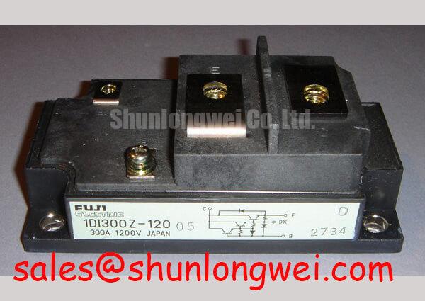
1DI300Z-120 Identification and Service Checks
- Isolate the drive and verify that the DC link is fully discharged before touching the power stage.
- Record cold-state terminal resistance readings and compare the three-phase paths for abnormal imbalance.
- Inspect the power transistor module mounting surface, busbar seating, and driver isolation path.
- Confirm that the replacement identification matches Fuji Electric 1DI300Z-120, rated at 1200.0 V and 300.0 A.
The 1DI300Z-120 is a Fuji Electric Power Transistor Module for high-power switching stages. The listed electrical ratings are 1200.0 V and 300.0 A. These are product identification values, not a complete operating envelope; switching frequency, cooling, transistor-drive conditions, overload behavior, and the surrounding protection network remain system-level design factors.
| Manufacturer | Fuji Electric |
| Model | 1DI300Z-120 |
| Category | Power Transistor Module |
| Rated voltage | 1200.0 V |
| Rated current | 300.0 A |
Benchtop Waveform Tuning: Mitigating Stress via Antiparallel Freewheeling Diode Reverse Recovery on 1DI300Z-120
Reverse-recovery behavior in the commutating antiparallel freewheeling diode should be assessed at the same commutation conditions used by the drive, because peak reverse-recovery current and high recovery slope can create voltage overshoot, ringing, and unwanted electromagnetic emissions. A current probe and a properly rated differential voltage probe allow the technician to compare turn-on current with the corresponding switch-node transient.
Keep the commutation loop physically compact and route the transistor-drive return with its intended reference path. The snubber network, if required by the measured waveform, should be connected at the switching-current loop rather than placed remotely on the control board. An RC snubber is an engineering recommendation for damping ringing, not an official parameter of this module. Its value should be selected from measured overshoot, dissipation, switching loss, and thermal results.
The transistor-drive network is another tuning variable. Confirm the transistor type and its required drive method against the device documentation before adjusting the drive strength or switching transitions. Slowing turn-on can reduce current-edge aggressiveness, but may increase switching loss and device temperature. Adjust the drive network only after confirming the driver output, isolation behavior, and turn-off margin. The Fuji Electric V-Series IGBT Application Manual provides background on switching-loop behavior, but its IGBT gate-drive recommendations do not establish the drive requirements of the 1DI300Z-120.
When a drive shows repeated overvoltage trips, inspect the oscilloscope trace for probe-loop artifacts, busbar inductance, diode recovery interaction, and drive-circuit oscillation before changing protection values. A MOV may be used as part of the broader overvoltage absorption network, but its clamping level, pulse energy, coordination, and fuse protection must be determined from the complete DC-link design.
1DI300Z-120 Thermal-Electrical Optimization: Symmetrical Busbar Geometry for High-Current Practical Tuning
Symmetrical busbar geometry helps reduce unequal stray inductance when multiple switching paths operate together. Keep high-current conductors arranged with balanced physical length and avoid routing one transistor-drive loop across a noisy collector or emitter path. The terminal identity must be confirmed against the original equipment drawing before energizing the replacement; a visually similar power layout does not establish electrical interchangeability.
Do not assume that parallel devices will share current through a positive temperature coefficient. Static sharing depends on the device’s on-state characteristics at the actual operating current and temperature, while dynamic sharing depends on drive-loop impedance, driver timing, commutation layout, and thermal coupling. During commissioning, compare phase-current waveforms and switch-node behavior rather than relying only on resistance measurements. Where devices are paralleled, also check current sharing between the individual branches.
Maintain suitable creepage and clearance around the high-voltage terminals, taking the working voltage, pollution environment, enclosure, and applicable equipment standard into account. These distances are system insulation design considerations, not a fixed dimension stated by the supplied product data. For a different current and voltage class, engineers may also evaluate the neutral listing for 6DI50AH-050, subject to a complete electrical, mechanical, and control-interface comparison.
Driver isolation deserves the same attention as the copper layout. The optocoupler or digital isolator, where used, must tolerate the measured common-mode transient environment, while dead-time control should prevent cross-conduction under the actual driver propagation spread, transistor turn-off behavior, and temperature range. A semiconductor fuse should be coordinated with the system short-circuit response and the module’s documented fault withstand limits; fuse I2t alone does not define safe interruption for every fault topology.
Field Diagnostics & Commissioning: Optimizing Heatsink Contact Pressure and TIM in 1DI300Z-120 Topologies
Thermal contact quality is established by a flat, clean heatsink interface, uniform thermal-interface-material coverage, and controlled mechanical fastening. As a general design consideration, a thin and continuous TIM layer in the approximate 50–100 µm range may be evaluated where the interface material and surfaces support it; the final thickness is governed by surface flatness, material instructions, and the assembly process.
Check the heatsink for burrs, contamination, and local curvature before placing the module. Apply the mounting sequence progressively and diagonally so that contact pressure develops evenly across the baseplate. Use the fastener torque specified by the module or equipment documentation; do not substitute a generic torque value without confirming the bolt size, washer arrangement, thread condition, and mounting interface.
⚠️ Field Alert: Never insert or remove the transistor-drive connector while the power stage is energized, and verify the isolation barrier before applying the DC link.
After mechanical assembly, inspect for TIM squeeze-out into unwanted areas, busbar strain, and terminal movement caused by vibration. Thermal imaging during a controlled commissioning run can identify phase-to-phase temperature differences, but interpret the image with emissivity, airflow, and load balance in mind. For topology-related waveform interpretation, the Resonant Topologies in Home Appliances reference offers useful background on commutation paths and switching-node behavior.
The Fuji Electric PIM 7-Pack reference can also help engineers distinguish general power-module integration principles from the specific construction and ratings of the 1DI300Z-120. Any use in a heavy-duty variable-frequency AC motor drive should be released only after electrical, thermal, mechanical, and protection checks are completed on the actual equipment.