Content last revised on October 21, 2026
1MBI400NB-120 Identification and Maintenance Checks
- Isolate the power stage, verify DC-link discharge, and disconnect external paths before taking cold-state terminal measurements.
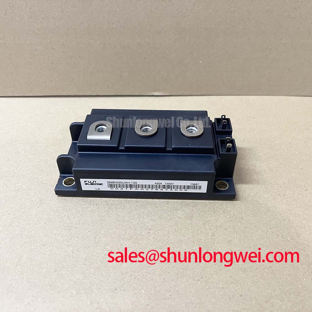
- Match the 1MBI400NB-120 marking to the equipment parts record and inspect terminal seating, mounting surfaces, and busbar alignment.
- Check the heatsink air path for contamination and inspect accessible insulation surfaces for moisture, tracking, or mechanical damage.
- Trace the gate-drive connections against the equipment schematic before reconnecting control wiring.
The Fuji Electric 1MBI400NB-120 IGBT module has a specified voltage rating of 1200 V and current rating of 400 A. These are the starting identification parameters for maintenance planning and replacement assessment, not a complete operating envelope.
| Parameter | Specified value | Parameter identity |
|---|---|---|
| Manufacturer | Fuji Electric | Product identification |
| Model | 1MBI400NB-120 | Product identification |
| Rated voltage | 1200 V | Official Specification |
| Rated current | 400 A | Official Specification |
| Device type | IGBT power module | Product identification |
| Terminal drawing, rating conditions, thermal limits, mounting instructions, and insulation test conditions | Consult Datasheet | Required integration documentation |
Preventing Spurious Faults: Assessing Suspected Ceramic Substrate Microcracks in 1MBI400NB-120
Separate surface contamination from suspected internal insulation damage before interpreting a terminal-to-baseplate measurement. As a Design Consideration, conductive dust, moisture, connected suppression components, and external wiring can alter the measured result. Record the disconnected configuration, instrument settings, environmental conditions, and measured behavior so that subsequent checks compare the same electrical path.
An insulation-resistance reading does not independently identify a ceramic microcrack. It assesses leakage under the applied test conditions; internal defect identification requires a qualified failure-analysis method. Likewise, a clean external surface does not establish the condition of an internal substrate. Keep the maintenance record descriptive: document where leakage was measured and whether it changed after approved cleaning and drying, rather than assigning an unverified internal failure mechanism.
Use only the applicable manufacturer-approved insulation procedure, including terminal grouping, test voltage, duration, and discharge method. An equipment-level insulation-test setting should not automatically be applied across a disconnected semiconductor module or its gate circuit. Insulation resistance and dielectric withstand are different assessments, so their acceptance criteria are not interchangeable.
For clearance and creepage assessment, inspect the installed assembly rather than the package alone. Busbar edges, displaced insulating barriers, loose conductive debris, and contaminated fasteners can affect the external insulation path. Required distances depend on the equipment insulation coordination, operating environment, and applicable standard. In damp service areas, address condensation and enclosure contamination before interpreting recurring isolation alarms as a module defect.
1MBI400NB-120 Thermal-Electrical Optimization: Sizing Braking Resistors and Assessing Chopper Duty
Establish the braking energy path from the equipment schematic before assessing whether this module is appropriate for the chopper position. During regenerative deceleration, energy can raise the DC-link voltage; a braking chopper controls energy dissipation in its resistor. The resistor, switching device, protection, and cooling arrangement must therefore be assessed together, rather than selected from the module current rating alone.
As an Engineering Recommendation, evaluate deceleration energy, repetition rate, resistor pulse capability, and cooling recovery against the equipment duty cycle. The resistor resistance also influences chopper current at the actual link voltage. Its thermal contact or temperature protection, where fitted, belongs in the review because an electrically intact resistor can still operate outside its permitted thermal duty. Fuji Electric’s Brake Chopper IGBT Modules resource provides manufacturer context for this application category; it does not establish this model’s terminal arrangement or equipment compatibility.
Before assembly, reconcile collector, emitter, and gate connections with the terminal drawing. Check that busbars sit without forcing the terminals sideways and that insulating barriers retain their intended position after tightening. For vibration-exposed assemblies, use the equipment-approved fastening and retention method, with calibrated tools and the specified tightening sequence. Extra torque is not a substitute for correcting poor alignment.
During planned outages, inspect heatsink fins, fan performance, mounting contact, and accessible thermal-interface edges. Base thermal-interface replacement intervals on the equipment maintenance plan and observed deterioration rather than an invented universal service period. Maintenance Note: Trend terminal temperature rise under comparable load conditions and check cooling airflow before attributing a rising temperature solely to the module.
For replacement assessment, compare 1MBI400L-060 as a separate candidate requiring its own voltage, circuit, mounting, and driver review, not as an automatic substitute. Evaluation for high-speed rail or heavy-freight locomotive traction inverters additionally requires the equipment owner’s electrical, environmental, and qualification requirements; the stated ratings alone do not establish suitability.
Transient Dynamics & Electrical Design: Kelvin Emitter Connection on 1MBI400NB-120
Trace the gate-driver return to its actual emitter connection before changing gate components to address oscillation. As a Design Consideration, inductance shared by the power-current path and driver return can produce a voltage that disturbs the effective gate-emitter drive during switching. Reducing that shared path can improve control, but the connection must follow the module’s documented terminal arrangement.
A dedicated auxiliary emitter terminal must not be assumed from the model designation. Where the terminal drawing identifies a separate driver-return connection, preserve its separation from the high-current emitter route. Otherwise, assess the documented connection and physical return path without inventing an additional terminal or modifying the package. Keep the outgoing gate connection and its return close together while maintaining the required separation from power conductors.
Investigate switching behavior with appropriately rated differential measurement equipment and a controlled test procedure. Probe placement and loop pickup can exaggerate apparent gate ringing, so compare measurements at consistent reference points. Review turn-off collector voltage alongside gate-emitter behavior and driver protection activity. Any gate-network adjustment should be validated across the equipment’s intended load and thermal conditions, not accepted merely because one trace appears cleaner.
For extreme switching-margin assessment, distinguish circuit topologies before transferring test expectations. The discussion of Resonant Topologies in Home Appliances offers a topology comparison, not an acceptance standard for this module. In motor-drive integration, cable reflections also belong to the complete inverter, cable, and motor assessment; assess any required filtering from measured terminal stress rather than applying a fixed overshoot assumption to the device rating.
1MBI400NB-120 Operational Boundaries: Evaluating Coordination of High-Speed Fuse Arcing Voltage Limits
Compare the protection fuse’s DC interruption characteristics with the actual DC-link circuit before treating its current rating as evidence of semiconductor protection. As a Design Consideration, available fault current, circuit time constant, capacitor discharge energy, and fuse arcing voltage all influence the interruption event. A fuse suitable for a different supply arrangement may behave differently in this circuit.
Total clearing I²t describes the fuse’s current-squared time integral through the interruption process. It is useful for coordination only when compared with applicable withstand information under compatible conditions. Do not assign a surge-current or sub-cycle withstand capability to the 1MBI400NB-120 from its 400 A rating, or transfer a diode surge rating to the IGBT switching path. Fuse coordination alone cannot guarantee prevention of module case rupture.
Review driver fault detection and controlled shutdown together with upstream interruption. The driver addresses semiconductor switching stress, while the fuse and isolation arrangement address fault energy according to their validated duties. During protection testing, assess transient voltage across the relevant components, including the effect of fuse arcing and busbar inductance. Keep these measurements within a qualified test plan rather than reproducing destructive faults during routine maintenance.
Before return to service, record the installed fuse designation, protection settings, busbar condition, insulating-barrier placement, and the approved functional-test result. If a fault has occurred, inspect the surrounding driver, DC-link connections, and braking circuit as well as the module. Restore operation only after the equipment’s protection sequence and isolation arrangement have passed the applicable service checks.