
Content last revised on October 8, 2026
Sizing Braking Resistors and Chopper Transistors for High-Dynamics Servos
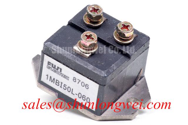
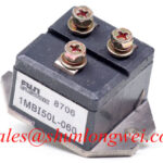
Isolate the servo drive, discharge its DC link according to the equipment service procedure, and check the installed module’s part marking before evaluating a braking fault. The 1MBI50L-060 is a Fuji Electric IGBT module with a rated voltage of 600 V and rated current of 50 A, both Official Specifications supplied for this product. Those ratings identify the device for an initial parts comparison; they do not establish that the module contains a braking circuit or that it can absorb a particular motor’s deceleration energy.
In a light industrial automation cell with a multi-joint robotic articulator, repeated stops can return energy from the motor to the DC link. Whether that energy is handled by a drive-integrated braking stage or a separate chopper depends on the installed equipment. For a repair assessment, trace the drive schematic from the DC-link terminals to the braking transistor and resistor before assigning a function to any module. Check the resistor’s documented resistance, pulse-energy capability, and cooling arrangement against the servo manufacturer’s braking requirements. These are system-level checks, not additional ratings for the 1MBI50L-060.
A resistor that has changed value, a disconnected braking path, and a control signal that never reaches the chopper can produce similar DC-link overvoltage symptoms. With power safely removed, inspect the braking connections and compare resistance measurements with the machine documentation. During an authorized powered test, record the DC-link trend and braking command through a controlled deceleration cycle. Stop the test if the equipment’s specified limits are approached. Keep resistor heat away from cable insulation and observe the enclosure clearances specified for that drive.
Fuji Electric’s brake chopper IGBT module information is useful context when identifying the role of a dedicated chopper stage. It is not a substitute for confirming the installed topology. The 1MBI300L-060 can be examined as another device in a topology review, but its gate-drive needs, connections, and mechanical fit must be checked independently rather than inferred from a shared model-family designation.
DC-Bus Low-Inductance Laminated Busbar Design & Turn-Off Voltage Overshoot Suppression
When replacing the 1MBI50L-060, photograph the existing DC-link and module connections before disturbing them. Preserve the original conductor routing unless an approved equipment drawing calls for a change. A long or widely separated current path can increase stray inductance; during turn-off, the associated voltage overshoot adds to the DC-link voltage seen by the switching device. The module’s 600 V rating is an Official Specification, while the acceptable operating DC-link voltage and switching margin must be established from the drive design and measured transients.
As a Design Consideration, closely coupled supply and return conductors and short connections to the specified snubber help contain the switching loop. They do not establish a universal busbar-inductance target for this module. Use the equipment drawings to confirm conductor spacing, insulation barriers, creepage and clearance requirements, and the location and ratings of any film capacitor. Do not relocate a snubber solely because a shorter physical path appears attractive: terminal function, service access, and the drive’s insulation design also matter.
If a drive trips after a module change, compare DC-link voltage and turn-off waveforms with the approved reference setup, using a probe and measurement method suitable for the circuit. Look for changes in peak voltage, ringing, or connection temperature rather than treating every trip as a failed semiconductor. Check busbar seating, fastener condition, and capacitor connections with power isolated. A comparison part such as 1MBI200NH-060 requires its own electrical, terminal, and mounting review; a similar voltage-class designation alone does not establish interchangeability.
Dynamic Gate Impedance Control for Robust Phase-Leg Dead-Time Operation
Before reconnecting a gate driver, identify the installed module terminals from the original Fuji Electric documentation and the drive schematic. The supplied Official Specifications for the 1MBI50L-060 establish 600 V, 50 A, and a module package; they do not specify gate resistance, gate-bias voltage, terminal assignments, or an active Miller clamp. Those details must be verified before changing the driver or interpreting a gate-to-emitter measurement.
Fast voltage transitions elsewhere in a phase leg can couple into an off-state gate through the device’s capacitance. The resulting gate disturbance is one possible contributor to unintended conduction, but a drive trip does not prove that mechanism. As a Design Consideration, review the gate-return path, driver supply stability, dead-time control, and any clamp function already present in the equipment. The choice of off-state bias and gate impedance belongs to the drive design and should be validated with switching measurements under its specified operating conditions. Fuji Electric’s RC-IGBT module information provides technology context, not a gate-drive setting for this particular part.
For a repeatable fault investigation, record which axis and operating state produce the trip. Then compare driver commands and gate waveforms with a functioning channel where the equipment permits that comparison. Inspect the gate connector and return connection for looseness, contamination, or damaged insulation. Keep measurements referenced to the correct local gate circuit; an apparent spike can otherwise be a measurement artifact. Do not adjust dead time or gate damping to suppress a symptom until the waveform, circuit path, and drive requirements have been reconciled.
⚠️ Maintenance Note: With power isolated, inspect and clean the heatsink and check mounting contact and terminal tightness against the equipment service instructions before attributing rising operating temperature to the module.
Calculating Failures-in-Time (FIT) Rates in High-Altitude Solar and Wind Farms
Do not calculate a FIT rate or predict a service life for the 1MBI50L-060 from its 600 V and 50 A Official Specifications. Such a calculation would require applicable device reliability data, operating voltage and temperature profiles, site conditions, and a stated calculation method. None of those inputs is established by the supplied product ratings. This is particularly important when a spare-parts review spans different equipment types: a robotic servo cabinet and a remote energy installation do not have interchangeable duty profiles.
Altitude-related cooling changes and radiation-related effects can be considered in a system reliability review, but they cannot be converted into a module-specific derating rule or single-event burnout rate without authoritative device data. For an installed drive, document its actual DC-link operating range, enclosure temperature, cooling condition, and relevant site requirements. Ask the system designer to assess voltage margin and environmental suitability using the equipment and semiconductor documentation applicable to that installation.
For routine maintenance in an automation cabinet, trend heatsink condition and connection temperature, inspect for moisture or condensation after shutdowns, and compare recurring fault records with measured electrical conditions. Dry or disturbed thermal-interface material warrants inspection under the equipment’s mounting procedure; appearance alone does not quantify thermal resistance. Where a trip remains unexplained, the Field Engineer’s Handbook provides a structured route for testing and failure analysis. Record the measurements and their operating conditions so the next technician can distinguish a changing installation condition from an unverified reliability assumption.