

Content last revised on October 2, 2026
Preventing Spurious Faults: Junction-to-Case Thermal Network Simulation Guidelines for MG50G1BL3
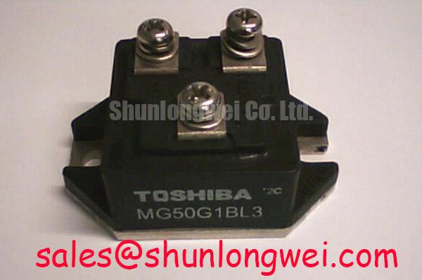
| Manufacturer | Toshiba |
|---|---|
| Model | MG50G1BL3 |
| Product Category | IGBT Module |
| Rated Voltage | 600.0 V |
| Rated Current | 50.0 A |
| Package | Toshiba Module |
Measure the module case temperature near the mounting surface and compare it with the switching load profile before attributing intermittent protection trips to the IGBT itself. The MG50G1BL3 is specified as a Toshiba IGBT module with a 600.0 V rated voltage and 50.0 A rated current; these are official device ratings, not a complete thermal operating limit for a finished inverter.
For pulsed overload analysis, use the manufacturer’s verified thermal data when building a junction-to-case RC network. A transient model should follow the actual pulse width, repetition pattern, case temperature, and cooling boundary rather than relying only on a steady-state thermal estimate. If the required thermal-resistance or transient-impedance data is not available for the exact assembly, treat the simulation as a design estimate and confirm it with thermocouple or infrared measurements during controlled switching tests.
At the bench, inspect the baseplate contact pattern, mounting flatness, thermal interface coverage, and terminal tightness. Uneven contact can create local heating that a remote heatsink sensor will not reveal. Keep high-current paths physically compact and separate the gate-control return from noisy power-current conductors. This is a Design Consideration for suppressing false desaturation or overcurrent responses; the final clearance and conductor arrangement must be determined from the inverter layout and verified under worst-case commutation.
Gate-drive commissioning should include a direct check of turn-on and turn-off waveforms at the module terminals. A distorted gate waveform, excessive common-mode movement, or unstable auxiliary supply can resemble a thermal fault. When a bootstrap driver is used, confirm that the bootstrap capacitor receives sufficient refresh time and that the charging diode recovery behavior does not disturb the gate supply during high-frequency operation. The correct capacitance, diode type, and switching frequency remain system-dependent.
⚠️ Field Alert: Remove power and allow the DC link to discharge before disconnecting gate-drive or power terminals, then follow the equipment’s verified discharge procedure.
Transient Dynamics & Electrical Design: Suppression of DC-Link Voltage Doubling on MG50G1BL3
Capture the collector-emitter waveform at the module terminals with a properly referenced high-voltage differential probe when a compact inverter shows unexplained overvoltage trips. Long motor leads, impedance discontinuities, and cable resonance can produce terminal overshoot that is not visible at the DC-link capacitor.
A reflected-wave event can raise the local voltage toward a multiple of the applied DC-link voltage, depending on cable length, termination, motor impedance, switching edge rate, and measurement position. This is a Design Consideration rather than an MG50G1BL3 datasheet claim. Minimize the commutation loop area, place the local high-frequency DC-link support close to the switching path, and verify the measured peak against the module’s 600.0 V official voltage rating during actual switching conditions.
Output filters and motor chokes should be selected from the complete drive topology. Their impedance, saturation behavior, thermal load, and interaction with cable capacitance must be evaluated together. Do not assign a universal filter value to this module. The system engineer should verify dv/dt, reflected-wave behavior, motor insulation stress, and current ripple with the intended cable and motor combination.
Check complementary gate signals on the same time base and confirm that the interlock prevents simultaneous conduction. Dead-time is a system-controlled timing parameter affected by driver propagation delay, temperature, gate resistance, and device turn-off behavior. A practical commissioning method is to begin with conservative timing, observe switching-node behavior, and then optimize it against shoot-through current, diode recovery, output distortion, and switching loss.
Gate-loop routing should keep the drive signal and its return path tightly coupled while avoiding the high-current commutation loop. Negative turn-off bias may be considered where the driver and module application require stronger immunity to common-mode noise, but its voltage and transient behavior must be verified from the selected gate-driver design. Do not assume a gate-voltage range that is not documented for the exact device and application.
For welding inverter and high-current switching context, engineers may consult Welding Power Supply High-Current Inverters. Current feedback can also be evaluated with industrial transducers such as those described by LEM High-Precision Current Transducers for Power Inverters, subject to bandwidth, isolation, and control-loop compatibility.
MG50G1BL3 Thermal-Electrical Optimization: DC-Bus Operating Voltage Headroom Derating Practical Tuning
Record the actual DC-bus voltage, switching current, case temperature, and fault timestamp together when an inverter operates near its voltage boundary. The MG50G1BL3 carries an official 600.0 V rated-voltage specification, but safe system operation also depends on overshoot, repetitive stress, temperature, switching conditions, insulation coordination, and the complete protection architecture.
Altitude and terrestrial neutron exposure can be relevant Design Considerations in high-voltage power electronics, particularly where the application operates above typical installation conditions. No device-specific SEB probability, FIT value, or altitude derating curve should be inferred without an authoritative source for the exact part and package. The correct engineering method is to identify the applicable reliability data, evaluate the DC-bus transient distribution, and validate the result through the equipment manufacturer’s qualification process.
For a compact industrial inverter or high-speed CNC spindle drive, tune the DC-bus operating point using measured peak voltage rather than nominal bus voltage alone. Check rectifier behavior, regenerative rise, snubber performance, and line-side harmonics during acceleration and deceleration. A phase-controlled rectifier can alter conduction angle and introduce input-current distortion; harmonic mitigation should be selected at system level using the line impedance, power rating, compliance target, and control method.
Short-circuit protection also requires coordinated timing. A desaturation circuit may command a soft turn-off to limit collector-current interruption stress, while the external fuse must interrupt the fault energy within the semiconductor and busbar limits. Fuse selection should compare the prospective fault current and the fuse I²t characteristic with the actual short-circuit withstand capability documented for the module and gate driver. A generic I²t number cannot be assigned to MG50G1BL3 from its voltage and current ratings alone.
Keep the control ground, current-sensor return, and gate-drive reference arranged to limit common-mode ground bounce. The use of shielding, isolated feedback, and negative gate bias is a Design Consideration that must be checked against driver isolation, turn-off transients, and control-board creepage and clearance. For wider background on fast-switching semiconductor design trade-offs, see Wide Bandgap Revolution.
Field Diagnostics & Commissioning: Regenerative DC-Bus Voltage Surge Dissipation in MG50G1BL3 Topologies
Measure the DC-link rise during a controlled deceleration cycle and correlate it with motor speed, load inertia, braking command, and fault timing before changing the power module. A regenerative surge can originate in the motor, braking branch, control sequence, DC-link capacitor condition, or wiring inductance, so a single symptom should not be assigned to one component without waveform evidence.
The braking path must be evaluated as a complete energy system. The braking IGBT, ballast resistor, switching frequency, thermal duty cycle, DC-link capacitor, and fault logic all determine whether deceleration energy can be absorbed safely. Resistor selection should be based on the motor’s recovered kinetic energy and the permitted DC-link voltage window, while the braking transistor must be checked for peak current, repetitive pulse energy, voltage overshoot, and cooling conditions. These are Engineering Recommendations for system evaluation, not additional factory ratings for MG50G1BL3.
During commissioning, verify the brake command threshold, gate-drive isolation, pulse timing, resistor temperature, and DC-link waveform with the motor unloaded and then under representative inertia. Confirm that the braking branch cannot remain continuously active after a control fault. Where the module is used in a topology with an external braking device, the integrator should verify electrical compatibility rather than assuming that the module’s 50.0 A rating directly defines braking-resistor current.
Inspect the power terminals and bus structure for discoloration, looseness, cracked insulation, or evidence of localized heating. A clean cold resistance check can help identify an obvious shorted semiconductor, but it cannot validate dynamic switching performance. Compare gate timing, collector-emitter voltage, current feedback, and protection response against a known-good operating cycle before returning the drive to service.
For a neutral replacement assessment within Toshiba-related industrial power assemblies, engineers can review MG150Q1JS40 as a separately specified device and verify mechanical, electrical, gate-drive, and thermal compatibility before considering any substitution.