Content last revised on October 3, 2026
7MBP50NA060 Thermal and Electrical Boundaries in Inverter Service
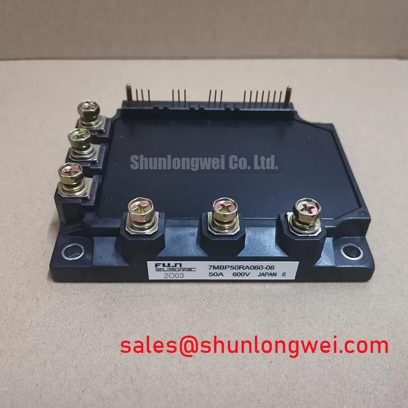
With the inverter isolated and its DC link discharged, check the 7MBP50NA060 terminal labels against the equipment schematic before making cold-state resistance or diode-mode measurements. Fuji Electric identifies this part as a module with a 600 V voltage rating and a 50 A current rating (Official Specifications). Those ratings establish the first screening boundary for a repair; they do not establish the installed circuit’s pinout, gate-drive requirements, thermal limit, or suitability as a substitute for another module.
Start the incoming check at the terminals. Record the part marking, terminal condition, and polarity shown in the original equipment documentation. With the module disconnected from its driver and power circuit, compare cold-state readings between corresponding paths using the same meter range and probe orientation. A diode-mode reading is useful as a repeatable comparison, but it is not an acceptance limit unless the applicable service documentation supplies one. An unexpected open, short, or asymmetry calls for confirmation against the circuit schematic and a known-good reference before the module is energized.
💡 Bench Tip: Keep the gate terminals protected from electrostatic discharge, and log probe polarity alongside every cold-state reading so the next technician can reproduce the comparison.
The 600 V rating is an Official Specification, not a permitted DC-link setpoint. As a Design Consideration, switching overshoot must be assessed in the installed inverter, where bus voltage, current, commutation-loop inductance, and control behavior interact. Capture the relevant voltage waveform under controlled switching conditions and compare its peak with the documented device boundary. A compact industrial inverter or high-speed CNC spindle drive is a potential compatibility assessment case, not an application guarantee.
Thermal contact deserves the same measured approach. Inspect the mounting face and heatsink for contamination, damage, and uneven contact before reassembly. As a Design Consideration, use the equipment manufacturer’s thermal-interface method and fastening procedure; neither a grease thickness nor a bolt torque can be assigned to 7MBP50NA060 from the ratings provided here. Where several power paths share load, compare their temperatures and current waveforms rather than assuming that a positive temperature coefficient will ensure static or dynamic current sharing. The relevant characteristics and operating conditions must be verified in the applicable module documentation.
Altitude and atmospheric radiation can be relevant to a system reliability review, but the available product ratings do not support a 7MBP50NA060 single-event-burnout rate, failure-in-time figure, or altitude derating rule. Treat those questions as Design Considerations requiring documented device data and an equipment-level assessment. The Field Engineer’s Handbook provides a broader testing and failure-analysis reference without turning an unmeasured field concern into a module specification.
Tracing Spurious Faults and Common-Mode Switching Effects
If a drive reports intermittent faults after a module change, preserve the fault record before adjusting the gate circuit. Check the driver supply, command signal, fault output, and gate-to-emitter waveform against the original schematic. Compare those signals at idle and during controlled switching. A pulse coincident with a switching edge may point toward common-mode coupling, driver behavior, or the measurement setup; it does not, by itself, identify a fault inside 7MBP50NA060.
Driver isolation and common-mode transient immunity belong to the selected gate-driver assembly and its documented operating conditions. No reinforced-isolation rating or CMTI value for this module is established by the supplied 600 V and 50 A specifications. As a Design Consideration, review the driver’s own isolation documentation, maintain the equipment’s specified clearances, and verify that the measurement probes and grounding arrangement are appropriate before interpreting a narrow gate pulse.
A freewheeling path and its reverse-recovery behavior can influence switching waveforms in an inverter. Do not assign a diode recovery characteristic to this particular part without its circuit diagram and electrical data. Where an overshoot or ringing pattern appears, compare voltage and current captures with the known-good equipment record, then assess the commutation loop and any installed snubber. Snubber changes are system design decisions: they should be checked for their effect on switching stress and losses, not treated as evidence that the module independently meets an equipment EMC requirement. Fuji Electric’s PIM product information is a useful manufacturer-level reference for identifying the relevant module family; the exact circuit and limits still require the matching part documentation.
Checking Desaturation Protection Before Returning the Drive to Service
Before applying power, trace the equipment’s overcurrent-protection path from current sensing or collector-voltage sensing through the driver fault output to the controller shutdown input. The 7MBP50NA060 ratings supplied here do not specify a short-circuit withstand time, a short-circuit safe operating area, or an internal desaturation function. Accordingly, no detection deadline or soft-turn-off sequence should be presented as a guaranteed feature of this module.
With an appropriate test setup, verify that a simulated fault reaches the controller and that the driver responds as its own documentation describes. During controlled switching tests, observe the turn-off voltage peak and gate waveform together. As a Design Consideration, limiting loop inductance and managing turn-off speed can help control inductive overshoot, but the acceptable settings depend on the installed driver, bus, layout, and documented device limits. A slow or missing shutdown may arise from sensing, blanking, wiring, supply, or controller behavior; isolate those possibilities before assigning the symptom to the power module.
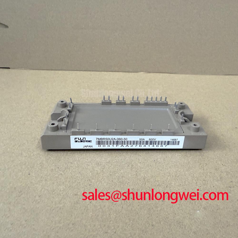
Measure on-state voltage only under conditions defined by the relevant electrical documentation. A cold diode-mode check cannot establish operating VCE(sat), and a single in-circuit voltage reading cannot separate device behavior from probe placement, current, and temperature. For a procurement comparison, 7MBR50LC060 can be reviewed as another model reference, but a shared voltage or current class would not establish interchangeability. Compare the complete terminal arrangement, circuit topology, driver interface, mounting, and thermal requirements against the original equipment specification.
Evaluating Gate Bias and Miller-Clamp Compatibility
A gate waveform that rises while its switch is commanded off warrants a measurement at the module terminals, referenced as closely as practicable to the associated emitter connection. Compare the event with the opposite switch’s transition and the DC-link waveform. This helps distinguish coupled switching behavior from a control-command error, although the result still depends on probe bandwidth and connection technique.
Negative gate bias and an active Miller clamp are possible driver-level approaches to unintended turn-on; neither is a confirmed requirement or built-in feature of 7MBP50NA060 on the supplied specifications. As a Design Consideration, assess the driver’s off-state impedance and clamp behavior against measured gate excursions, then confirm compatibility with the module’s documented gate limits. Fuji Electric’s discrete IGBT information offers general device context, but discrete-device guidance must not be substituted for this module’s part-specific limits.
⚠️ Field Alert: Disconnect power and verify DC-link discharge before moving gate-driver leads or probing module terminals. After reconnecting the driver, repeat the cold-state comparison where accessible, verify terminal-to-schematic correspondence, and check the fault path before a controlled switching test. The final gate-bias and clamp settings are determined by the equipment design and measured waveforms, not by the 600 V and 50 A ratings alone.