
Content last revised on October 12, 2026
Field Diagnostics and Commissioning for 2DI100Z-120 Rectifier Topologies
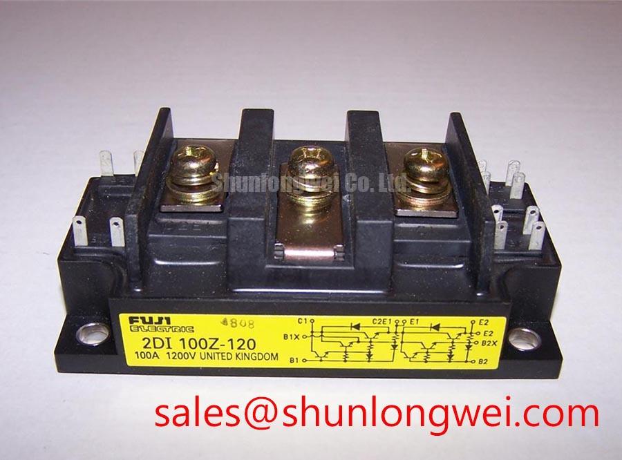
Before energizing a replacement rectifier, isolate the converter, inspect the mounting surface, and confirm that the marked power terminals match the original circuit position. The 2DI100Z-120 is a Fuji Electric power diode module with a specified voltage rating of 1200 V and a current rating of 100 A under the applicable datasheet conditions. Confirm its internal diode arrangement from the manufacturer’s circuit diagram; do not assume that an individual module contains a complete rectifier bridge.
This device is a diode module rather than a gate-controlled thyristor assembly. It therefore has no gate trigger current, gate threshold voltage, or gate-turn-off function to commission. Any service procedure that refers to gate pulses, negative gate bias, or multi-pulse firing belongs to a different semiconductor topology and should not be applied to this model.
For medium-frequency induction melting and metal hardening power supplies, the practical evaluation focuses on diode polarity, rectifier input routing, DC output connections, cooling conditions, fuse coordination, and transient behavior within the complete converter. The product category and electrical ratings should be checked against the equipment schematic before a field replacement is approved.
Commissioning should begin with a de-energized continuity and isolation inspection that follows the original rectifier wiring. Confirm the module’s anode and cathode connections from the manufacturer’s circuit diagram and equipment documentation rather than inferring terminal function from physical position. A rectifier assembly can show different forward conduction paths depending on the test lead arrangement, so a single resistance reading is not sufficient evidence of serviceability.
During a cold inspection, compare the replacement module’s terminal markings, mounting pattern, and housing condition with the removed unit. Check for cracked insulation, loose terminal hardware, contamination around the power connections, and uneven contact between the base and heatsink. Dimensions, internal circuit arrangement, thermal resistance, surge current, and fuse I²t coordination should be taken from the applicable Fuji Electric documentation for the exact device.
Because this is not a gate-controlled device, a firing-pulse oscilloscope trace cannot validate the module itself. Instead, monitor the rectifier input and output under controlled commissioning conditions, checking for abnormal phase imbalance, unexpected DC ripple, and voltage overshoot at the module terminals. The switching environment, bus inductance, transformer leakage, and protection network can all influence the measured waveform.
When the rectifier is part of a larger induction heating cabinet, engineers may also review the upstream protection and power-control stage. The related 2DI300A-050 can be reviewed as a separate diode-module reference, but voltage, current, internal circuit, package, and thermal compatibility must be established from the complete circuit design rather than assumed from product naming.
Assembly Integrity and AC Surge Protection Architecture
AC input surge protection should be coordinated with the line voltage, transformer arrangement, prospective fault current, and protective fuse selected by the system designer. An MOV or RC network placed ahead of the rectifier may help control repetitive switching transients, but its clamping level, energy rating, leakage behavior, and failure coordination are system-level decisions. IEC 61000-4-5 test methods can provide a useful surge evaluation framework, but they do not by themselves establish that a complete induction furnace cabinet complies with an EMC or safety requirement.
For a diode module with a 1200 V rating, the measured reverse-voltage transient envelope must be assessed against the applicable datasheet limits and actual circuit conditions. Keep the high-current AC and DC paths compact and mechanically secure, while separating sensitive control wiring from rectifier conductors to reduce common-mode disturbance. The fuse selection should be checked against the manufacturer’s applicable coordination data, including prospective fault energy and repetitive surge conditions; a generic fuse value cannot be assigned from the 100 A rating alone.
Mechanical assembly affects electrical reliability. The heatsink should be clean, flat, and free from burrs before the module is secured, and the power terminals should be tightened according to the applicable Fuji Electric mechanical specification and the selected hardware. Safety interlock note: isolate and verify the discharge state of the DC link before touching the module, terminals, or heatsink.
Fuji Electric’s Global Power Semiconductor Technologies and its Power Semiconductors Portal are appropriate reference points for product-family documentation and application information.
Controlling Off-State Voltage Rise and Commutation Stress
A diode does not turn on through a gate command, but it can experience commutation stress when current transfers between phases or when the surrounding switching circuit produces a rapid voltage transition. An RC snubber, series reactor, or other damping network should therefore be selected from measured parasitic inductance, switching frequency, load current, transformer characteristics, and allowable semiconductor voltage margin.
Snubber tuning should be performed with suitable high-voltage probes and current measurement, comparing the waveform at the actual module terminals rather than at a remote busbar point. Excessive ringing may indicate layout inductance, an unsuitable damping network, or an interaction with the transformer and power-control stage. Excessive snubber loss can also increase cabinet temperature and reduce the available thermal margin.
In regenerative braking or energy-storage sections connected to the same power cabinet, the braking chopper and resistor bank must be evaluated independently from the rectifier. Confirm energy absorption, duty cycle, cooling, and fault isolation at system level. The diode module rating remains a component specification, not a complete statement of converter operating capability.
For broader topology context involving multilevel conversion, bus transients, and energy-storage interfaces, engineers can consult Peak Efficiency in Solar and Energy Storage. Any use of the 2DI100Z-120 in a medium-frequency induction melting or hardening furnace should be released only after terminal polarity, protection coordination, thermal behavior, and measured transient margins have been validated in the intended equipment.