Content last revised on September 25, 2026
Preventing Spurious Faults: Type 2 Coordination and Dead Short Guidelines
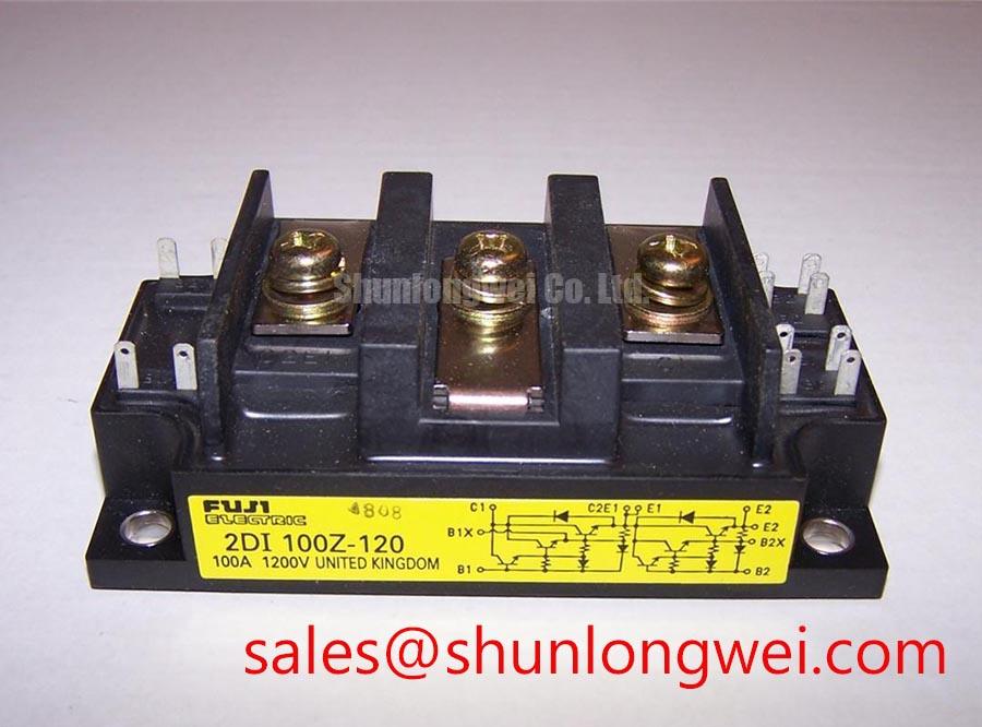
For a high-current green hydrogen electrolyzer DC power rectifier, semiconductor fuse coordination should be checked against the complete protection path rather than selected from the module current rating alone. The required comparison includes the fuse clearing I²t, prospective fault current, circuit impedance, bus capacitance, and the diode bridge’s published surge and short-duration withstand data. The available product information confirms the 1000.0 V voltage rating and 100.0 A current rating, but it does not provide a fuse I²t coordination table or a verified dead-short energy limit.
Designers should obtain the applicable Fuji Electric technical documentation before approving a Type 2 coordination claim. During maintenance, inspect fuse holders, busbar joints, and terminal surfaces as one electrical path. Uneven contact pressure can increase local heating and alter the fault current seen by the protective device. The same review can include the compatible 2DI100D-050C as a neutral cross-reference for maintenance planning, subject to voltage, current, mechanical, and protection compatibility checks.
Maintenance Note: Keep the heat sink and airflow path clean, then monitor contact temperature under representative load after terminal tightness has been checked against the manufacturer’s installation instructions.
Assembly Integrity and Layout Architecture for Power Factor and Harmonic Mitigation
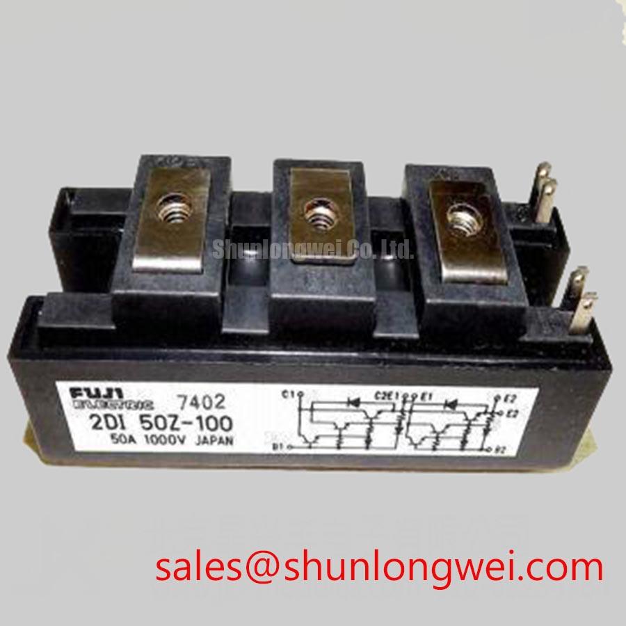
The module is a diode bridge, so its conduction pattern is determined by the applied AC waveform and the downstream DC link. A firing angle is associated with controlled rectifier operation and should not be treated as a built-in parameter of this diode module. If the 2DI100Z-100 is evaluated within a larger converter that includes controlled devices, the system engineer must analyze displacement power factor, commutation overlap, DC-link impedance, and harmonic current at the actual operating point.
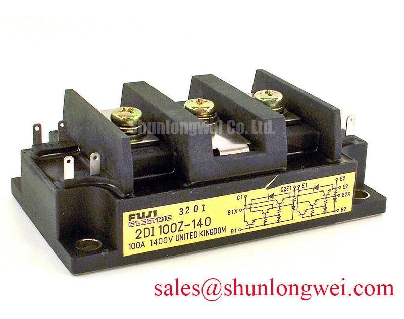
For electrolyzer rectifier service, layout review should begin at the AC terminals and continue through the shortest practical high-current path to the DC bus. Minimize stray inductance where possible to limit switching overshoot, then verify peak voltage with an oscilloscope during startup, load changes, and fault interruption. The associated 2DI100Z-140 may be reviewed as a related rectifier-stage device, but it should not be treated as an automatic substitute or complementary choice without checking the original circuit documentation.
Power factor correction, phase-shifting equipment, and harmonic filtering remain system functions. Their ratings depend on the transformer, converter topology, load profile, and grid requirements. The official Fuji Electric power semiconductor and IPM resource can be consulted alongside the specific module documentation when confirming the intended electrical arrangement.
RC Snubber Network Evaluation and Localized di/dt Protection
An RC snubber should not be assigned a fixed resistor or capacitor value from the 2DI100Z-100 name alone. The correct network depends on stray inductance, commutation behavior, source impedance, bus capacitance, and the measured voltage transient at the module terminals. A design consideration is to place suppression components close to the commutation loop and verify their power dissipation during the complete duty cycle.
Where a saturable reactor or other di/dt limiting element is present, the system designer should verify its effect during both normal current transfer and abnormal current rise. Oscilloscope measurements should compare turn-on and turn-off waveforms at the module terminals, with probe placement arranged to avoid adding significant loop pickup. If the required RC values, repetitive peak voltage, or transient limits are not stated in the applicable Fuji documentation, they must be established through controlled testing rather than assumed from another diode bridge.
Diode Peak Reverse Recovery Current, Softness, and EMI Review
The supplied factory parameters do not state reverse recovery peak current, reverse recovery time, or a quantified softness factor for the 2DI100Z-100. Those values should therefore be confirmed from the correct Fuji Electric datasheet revision before calculating commutation loss, snubber stress, or conducted and radiated EMI behavior. A diode’s reverse recovery response is influenced by junction temperature, forward current, rate of current change, and the external commutation circuit.
In the electrolyzer rectifier cabinet, verify the reverse recovery waveform at the actual AC source impedance and DC load. Look for the relationship between recovery current, voltage overshoot, heat sink temperature, and interference observed on nearby control wiring. Cable routing, enclosure bonding, and filter placement remain system-level engineering tasks; the diode module itself cannot be represented as independently compliant with an EMC standard. For gate-drive and switching-stage background relevant to adjacent controlled devices, engineers may consult Evolution of Negative Off-Bias Gate Drive Circuits and the Fuji Electric power semiconductor portal.