

Content last revised on October 1, 2026
Assembly Integrity & Layout Architecture: Coordinating Primary Spark Gaps and MOVs for 2DI150Z-140
| Manufacturer | Fuji Electric |
| Model | 2DI150Z-140 |
| Product Category | Power Diode Bridge Module |
| Rated Voltage | 1400.0 V |
| Rated Current | 150.0 A |
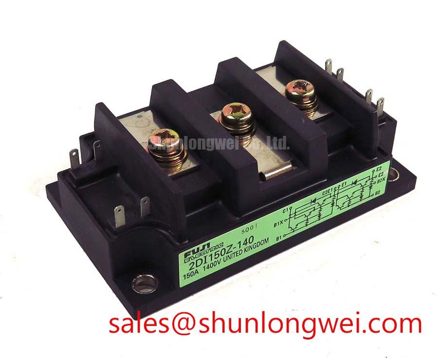
Measure the isolated resistance between the main terminals and the heatsink before connecting the module to an SVC power stage, then inspect the terminal faces, mounting surface, and insulation hardware for contamination or mechanical damage. The 2DI150Z-140 is a Fuji Electric Power Diode Bridge Module with an official rated voltage of 1400.0 V and rated current of 150.0 A.
In a grid-tied static Var compensator or thyristor-switched capacitor assembly, the diode bridge sits within a larger protection network. Primary spark gaps, MOVs, line reactors, and RC suppression stages must be coordinated with the actual system voltage, prospective fault current, surge waveform, and grounding arrangement. These are system-level design considerations rather than guaranteed characteristics of the diode module.
Place surge-limiting components so that their current paths do not share unnecessary wiring length with the high-current diode loop. The protection network should be checked for clamping behavior during controlled switching tests, while the semiconductor fuse selection should be compared with the manufacturer’s permissible peak-current and I2t data for the installed circuit. Do not infer fuse coordination from the 150.0 A rating alone.
Use the original equipment connection diagram to identify each power terminal and preserve the intended current direction. The mounting plate should be clean, flat, and compatible with the specified thermal interface material. Apply the manufacturer’s prescribed fastening method and torque for the actual hardware; an assumed torque value can distort the module base or reduce thermal contact.
Transient Dynamics & Electrical Design: Separating Adjacent Gate-Drive Circuits from 2DI150Z-140
Trace the firing circuit and confirm that the trigger wiring belongs to the associated thyristor stage rather than the diode bridge before analyzing a suspected gate-pulse fault. The 2DI150Z-140 is a diode module, so gate trigger current, gate pulse rise time, back-porch holding current, and multi-pulse gate-firing behavior are not terminals or functions of this product.
For a thyristor-switched capacitor cabinet using this bridge in an adjacent rectification or charging path, examine the gate circuit separately with an isolated measurement setup. A distorted trigger waveform may be affected by control-board timing, common-mode coupling, wiring inductance, or an unstable reference return. Verify the waveform against the known-good phase path and correlate it with the switching instant at the power terminals.
Long motor or cabinet cables can produce reflected-wave overshoot when their characteristic impedance and termination do not match the switching network. The practical design objective is to minimize the high-frequency loop area and control the rate of voltage change with a damping network selected from measured waveforms. The final values must be determined by the system engineer after checking peak voltage against the bridge’s voltage rating and the complete protection network.
For adjacent high-frequency conversion stages, the article The 1200 V CoolSiC™ MOSFET Advantage in Three provides useful background on switching behavior and power-conversion layout. It should be treated as application guidance, not as a specification for this Fuji Electric diode bridge.
Assembly Integrity & Layout Architecture: Evaluating High-Peak Thermal Stress for 2DI150Z-140
Record the heatsink temperature at the module base and compare it with the cabinet airflow condition while the SVC operates through its normal switching sequence. The official product data supplied for this page confirms a 1400.0 V rated voltage and 150.0 A rated current, but it does not provide a field lifetime, surge-current, or thermal-avalanche figure that can be stated here.
For a short sinusoidal overload event, engineers should identify the actual half-cycle current, repetition pattern, initial junction condition, and recovery voltage before judging semiconductor stress. A single peak-current observation is insufficient because repeated events can change the thermal state of the assembly and alter the available margin.
Review the semiconductor fuse data, clearing behavior, and coordination table supplied for the complete protection design. The fuse I2t value must be assessed against the applicable diode transient withstand information for the exact device revision and circuit configuration. If the original technical file does not contain those limits, measure the event with suitable isolated probes and obtain the missing limits from the applicable manufacturer documentation.
Clean the heatsink and inspect the thermal interface whenever contact temperature rises without a corresponding load change. Maintenance Note: Keep the airflow path clear and periodically compare module-base temperature across equivalent phases to identify deteriorating thermal contact. Engineers evaluating related rectifier positions may also review the neutral product page for 2RI100G-160, while electrical compatibility remains dependent on the original circuit and mechanical interface.
Assembly Integrity & Layout Architecture: Coordinating Short-Circuit Withstand Limits for 2DI150Z-140
With the cabinet fully isolated, inspect the semiconductor fuse, busbar joints, and diode terminals for evidence of a high-current interruption before applying any replacement power module. A short circuit in an SVC or capacitor-switching assembly can involve the bridge, upstream impedance, switching devices, fuse clearing time, and enclosure buswork as one event.
Coordinate the selected fuse with the actual prospective fault current and the module’s documented transient withstand limits. The 150.0 A rating identifies the device’s stated current class; it does not establish short-circuit survival or guarantee zero mechanical damage during a dead-short fault. The protection study should confirm that the fuse clears within the permissible semiconductor energy window and that the busbar arrangement limits secondary arc and pressure hazards.
Inspect terminal discoloration, loosened hardware, cracked insulating parts, and altered contact surfaces after a fault. These observations do not identify one certain failure mechanism by themselves, so compare them with phase-current records, fuse condition, gate-controller logs, and oscilloscope captures from the same cabinet.
Where an auxiliary or front-end rectification stage is involved, the 2RI100E-080 can be reviewed as a related power-semiconductor reference. It should not be treated as an automatic substitute for the 2DI150Z-140 without confirming voltage, current, topology, terminal arrangement, thermal path, and protection coordination. For industry-level semiconductor application context, consult Shindengen Power Semiconductor Modules & Diodes.