

Content last revised on October 4, 2026
2DI240A-055 Diode Bridge Checks
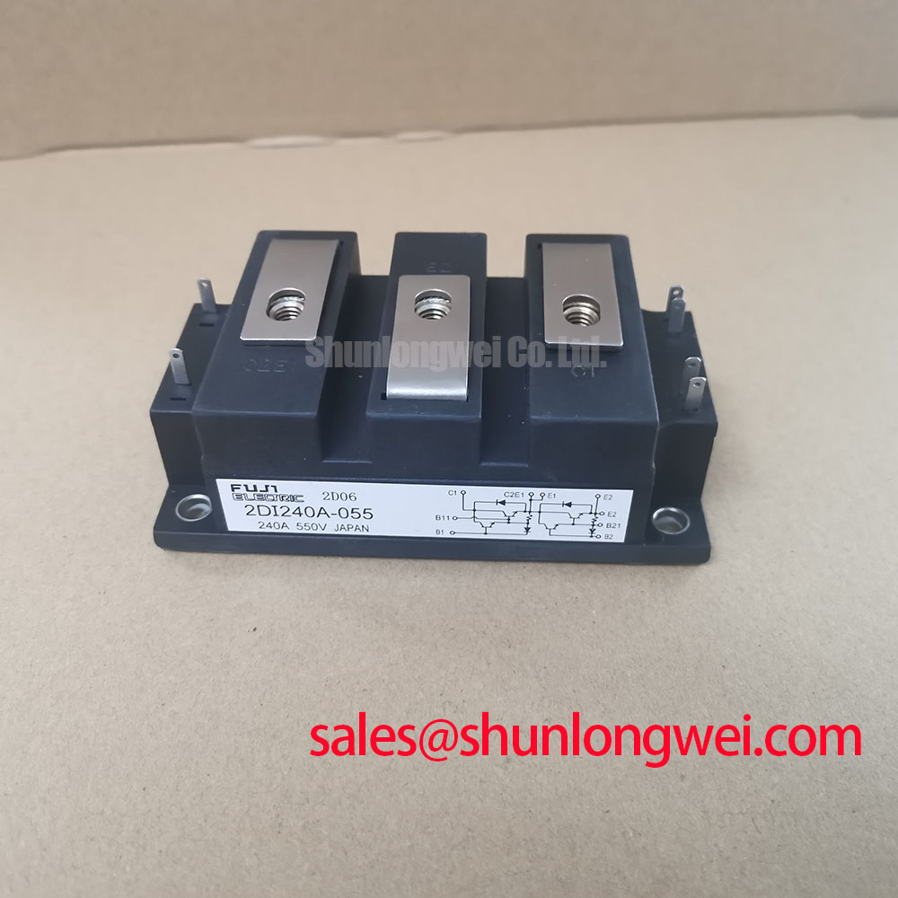
With the equipment isolated and its DC link discharged, compare the terminal markings of the 2DI240A-055 against the original circuit drawing before taking cold diode-mode readings. Record each conducting direction and compare it with a known-good unit or the documented bridge connections; a single reading does not establish the condition of the complete power stage. Fuji Electric identifies this device as a Power Diode Bridge Module rated at 550 V and 240 A (Official Specification). Those ratings establish the starting point for evaluation, not the voltage and current limits of an assembled furnace supply.
2DI240A-055 Mounting Contact and Thermal Checks
Inspect the mounting face, heatsink flatness and terminal hardware before energizing a replacement assembly. Uneven contact or displaced thermal compound can raise operating temperature even when cold diode-mode readings appear consistent. As a Design Consideration, apply thermal compound uniformly and tighten the mounting hardware in accordance with the original equipment and module documentation; no mounting torque or junction-to-case thermal resistance value is established by the supplied specifications. Do not treat an assumed copper baseplate construction as a verified feature of this part.
When investigating heat-related trips, capture heatsink temperature and load current under repeatable operating conditions. Compare the results with maintenance records and verify the cooling path before attributing the trip to the diode module. A temperature measurement at the accessible mounting surface is useful for comparison, but it is not a direct measurement of diode junction temperature. Engineers evaluating the module for a medium-frequency induction melting or hardening furnace should also confirm that the rectifier position, terminal layout and cooling arrangement match the equipment drawing.
Reverse Recovery and Commutation Faults
A diode transferring current during commutation can contribute to switching stress elsewhere in the converter. Reverse-recovery peak current and recovery time depend on the device and test conditions, but verified values for 2DI240A-055 are not present in the supplied specifications. They should not be inferred from its 550 V and 240 A ratings. If a repair follows repeated commutation faults, compare captured current and voltage waveforms with a known-good power stage while checking the DC-link, connection integrity and the switches involved in commutation.
Gate-off bias and common-mode ground noise concern the controlled switches in the surrounding circuit, not the terminals of this diode bridge. Likewise, a regenerative braking chopper or bidirectional battery converter must be assessed as a complete circuit rather than assigned to this module on the basis of its current rating. Fuji Electric’s PIM product information describes a different integrated power-module category; its topology and switching characteristics should not be transferred to the 2DI240A-055.
For fault isolation, keep display documentation separate from power-stage measurements. An operator-panel backlight issue, described in general terms by this LED backlight reference, cannot establish the condition of a rectifier module.
Incoming Inspection and Fuse Coordination
On the bench, map the marked terminals to the schematic, then take diode-mode readings across each accessible conduction path in both probe orientations. Record the meter, test polarity and cold-state results so another technician can repeat the comparison. An unexpected reading may involve a connected circuit path, a probe-contact problem or the module itself; isolate the module as the equipment service procedure permits before drawing a conclusion. If insulation withstand testing is required, obtain the applicable manufacturer instructions and keep the test method distinct from a routine multimeter check. The supplied specifications do not state an insulation test voltage or an insulation reliability rating.
💡 Bench Tip: Discharge and verify the DC link before connecting a meter to the module terminals.
Fuse selection requires the prospective fault current, the fuse’s clearing characteristics and the diode’s documented surge and I²t withstand data under compatible conditions. The supplied specifications contain no 2DI240A-055 I²t rating or fuse coordination table, so they cannot support a numerical clearing-energy comparison or a promise that a dead short will cause no damage. A Design Consideration is to check the installed fuse against the original equipment protection schedule and obtain the applicable module data before changing fuse type. Terminal connection and conductor routing should also be checked against the equipment drawing rather than inferred from another bridge module’s appearance.
Surge Rating, Reapplication and Replacement Fit
The 240 A Official Specification is a rated-current figure, not a stated non-repetitive surge-current limit. No verified sinusoidal half-cycle surge rating or initial junction-temperature condition is available in the supplied specifications. Before assessing an inrush or fault event, review the equipment’s captured current trace, protection operation and restart sequence, then compare them with the applicable device documentation. Confirm that the DC link has returned to a safe state before repeating static checks; a cold pass alone does not demonstrate adequate margin when reverse voltage is reapplied after a hot surge.
The 6RI75G-160B can appear in a broader parts comparison, but it should not be treated as a drop-in replacement without checking its circuit function, ratings, terminals, mounting and thermal requirements against the original design. For background on switching-device behavior in three-phase conversion, The 1200 V CoolSiC™ MOSFET Advantage in Three discusses a different device technology; its operating figures are not specifications for this Fuji Electric diode bridge. The final integration decision rests on the furnace schematic, the module documentation and measured conditions in the repaired equipment.