Content last revised on October 10, 2026
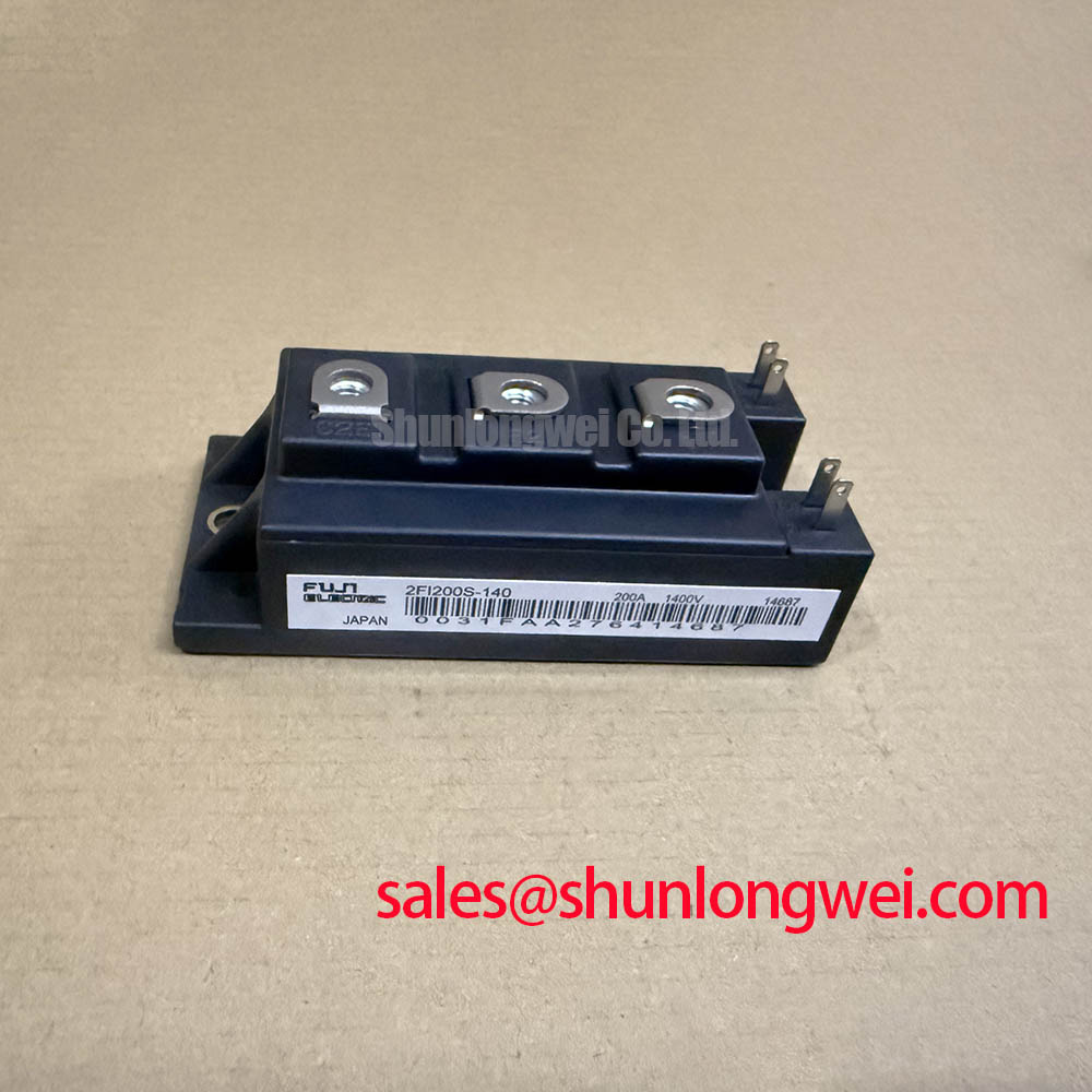
Benchtop Waveform Tuning and Insulation Screening for 2MBI200J-140
| Product model | 2MBI200J-140 |
|---|---|
| Manufacturer | Fuji Electric |
| Product category | IGBT Module |
| Rated voltage | 1400 V — collector-emitter voltage rating |
| Rated current | 200 A — collector current rating under the datasheet’s specified conditions |
| Package | Fuji Power Module |
| Integration reference | Consult the model-specific datasheet for terminal assignments, insulation test conditions, thermal characteristics, and mounting requirements. |
Disconnect the power terminals and gate circuitry from the surrounding equipment before evaluating terminal-to-baseplate insulation on the 2MBI200J-140. As a Design Consideration, establish the approved test connections, instrument voltage, dwell time, and acceptance criteria before applying an insulation tester. The module’s 1400 V electrical rating is not an insulation-test voltage, and connected drivers or monitoring circuits must not become unintended test paths.
Inspect accessible insulation surfaces for contamination, moisture, tracking, and mechanical damage. Airborne dust can affect surface leakage, especially when combined with condensation. Record the test configuration and environmental conditions so that subsequent measurements remain comparable. A change in insulation resistance warrants investigation, but resistance measurements alone cannot establish whether an internal ceramic substrate contains a microcrack. Internal construction and damage mechanisms require model-specific evidence rather than assumptions based on the package name.
Separate this insulation assessment from energized waveform testing. Once the assembly is cleared for operation, capture collector-emitter voltage and gate-emitter voltage with appropriately rated differential instrumentation. Compare switching edges under controlled load conditions, checking whether overshoot follows changes in current, bus geometry, or gate-loop routing. This helps distinguish a switching-layout problem from a leakage concern without assigning either symptom a single cause.
For sourcing comparisons, review 2MBI50-120 against the required electrical envelope, terminal drawing, and mounting interface. A related Fuji model number does not establish interchangeability; the comparison must retain the original equipment’s operating and protection requirements.
Preventing Spurious Faults: Coordination of High-Speed Fuse Arc Voltage for 2MBI200J-140
Evaluate the semiconductor fuse’s total clearing energy and arc voltage against the actual DC-link fault circuit before accepting a protection arrangement around the 2MBI200J-140. This is a Design Consideration: fuse coordination depends on prospective fault current, circuit inductance, operating voltage, and the fuse manufacturer’s DC interruption data. The module’s 200 A rating must not be treated as a short-circuit withstand specification or converted into a presumed allowable I²t.
Keep gate-driver fault response and fuse interruption distinct. A driver can terminate a controllable switching fault, while a fuse addresses the fault-current path within its specified interruption envelope. Evaluate their interaction, including current redistribution and voltage stress during interruption. Fuse selection alone cannot guarantee freedom from module case rupture; containment and protection performance require equipment-level validation.
When assessing a regenerative braking chopper, trace the current path through the switching device and braking resistor. The resistor assembly’s pulse-energy capability, temperature supervision, and connection integrity belong to the system assessment. Fuji’s Brake Chopper IGBT Modules page provides manufacturer context for that application category, not evidence that this specific module is a dedicated chopper product.
Where an upstream phase-controlled rectifier is present, examine its conduction pattern and the resulting DC-link ripple separately from the IGBT switching waveform. RC snubber evaluation should address measured ringing, capacitor pulse stress, and resistor dissipation. In a separate converter stage, 2MBI50J-060 can be included in a component review only after checking that stage’s requirements; it should not be assumed to serve as a rectifier or a matched companion.
Preventing Spurious Faults: Junction-to-Case Thermal Network Simulation Guidelines for 2MBI200J-140
Build the junction-to-case thermal assessment from the actual pulse sequence and device losses rather than using average load current alone. As a Design Consideration, separate conduction loss, switching loss, and any documented diode loss before applying the manufacturer’s transient thermal impedance data. Heavy overload pulses can produce junction-temperature excursions that a slowly responding case-temperature sensor does not resolve.
A multi-RC thermal model should reproduce the applicable transient thermal response over the pulse durations being evaluated. Engineering Calculation: estimate the junction-temperature rise by applying the time-dependent loss waveform to that thermal response, then add the case-temperature boundary condition. Include residual heat from preceding pulses when evaluating repeated overloads. Model coefficients must come from applicable manufacturer data or a validated characterization, not from another module with a similar current rating.
Inspect the mounting interface before attributing an unexpectedly high case temperature to semiconductor losses. Baseplate seating, heatsink flatness, thermal-interface coverage, and fastening sequence can influence heat transfer. Apply the specified assembly procedure rather than importing a generic bolt torque. Keep temperature-sensor placement consistent, and account for measurement delay when comparing bench results with the model.
For compatibility evaluation in commercial string inverters and micro-grid energy storage equipment, examine sustained converter duty alongside transient charging or discharge loads. The Fuji Electric IGBT Modules information offers context for contemporary module evaluation; thermal characteristics and technology claims for other product families must not be transferred to the 2MBI200J-140.
Assembly Integrity & Layout Architecture: Implementing Kelvin Emitter Connection for 2MBI200J-140
Trace the gate-driver return against the module terminal drawing before implementing any Kelvin emitter connection. As a Design Consideration, use a separately documented auxiliary emitter terminal where the device provides one; do not infer its presence from the model designation. If the connection is not available, arrange the external return path to reduce shared impedance without describing that layout as an internal Kelvin structure.
Shared emitter-path inductance can disturb the effective gate voltage during rapid current changes. Keep the gate drive and its return closely associated, separate them from high-current commutation paths, and evaluate the voltage at the module terminals. Miller-coupled current and common-mode ground movement can both contribute to unwanted gate excursions, so probe placement and measurement bandwidth matter when interpreting apparent oscillation.
Negative turn-off bias, if adopted by the system design, must remain within the device’s gate limits and the driver’s operating envelope. Where a bootstrap supply is used, assess charge replenishment during the actual switching sequence, capacitor discharge under driver load, and bootstrap-diode recovery behavior. An adequate supply measurement at idle does not establish sufficient gate-drive margin during prolonged high-side conduction.
Engineering Recommendation: Keep the commutation path compact and bus connections balanced where the topology permits, then validate turn-off overshoot with controlled double-pulse testing before increasing operating stress.
Use Precision Gate Drive Design to structure the driver review around return routing, damping, and protection timing. When troubleshooting repeated trips, correlate the gate waveform, collector-emitter waveform, and driver fault output on the same acquisition; this distinguishes protection activation from measurement pickup and identifies which event precedes the shutdown.