

Content last revised on October 2, 2026
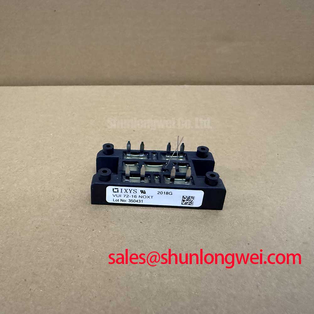
Transient Dynamics and Electrical Design: DC-Link Layout for VUI72-16NOXT
At turn-off, current in the connection between an IGBT module and its DC-link capacitor bank cannot stop instantaneously. Stray inductance in that path contributes to a voltage overshoot, so the measured device voltage can exceed the steady DC-bus voltage. Design Consideration: keep the capacitor-to-module current path compact, arrange outgoing and return conductors close together where the equipment layout permits, and evaluate the resulting peak voltage under representative switching conditions. The allowable geometry and clearance must come from the actual bus voltage, insulation design, and applicable equipment requirements rather than a generic inductance target.
For a repair, inspect the capacitor bank and its connections before attributing an overvoltage event to the module alone. Look for loosened bus joints, heat-discolored contact surfaces, displaced insulation, and changes to capacitor mounting that lengthen the current loop. Compare the installed busbar arrangement with the original equipment drawings. A replacement module with the same headline voltage and current ratings cannot compensate for a deteriorated DC-link connection.
If switching records or safe instrument access are available, capture the DC-link voltage and the relevant switching waveform using probes and procedures appropriate to the equipment. Compare the observed peak with the module’s 1600 V official voltage rating, while confirming from the full device documentation which terminals and test conditions that rating describes. Snubber selection, if the system uses one, belongs to the equipment design: capacitance, loss, placement, and fault behavior need validation together. Adding capacitance without checking the associated current path can shift stress rather than resolve it.
Where the equipment includes a phase-controlled rectifier upstream of the DC link, its firing behavior and resulting bus ripple are system-level checks, not stated features of the VUI72-16NOXT. Examine supply waveforms and rectifier controls against the machine documentation before linking unusual DC-bus behavior to the module. The same distinction applies to harmonic mitigation: it is assessed at the converter and installation level, not certified by an individual power module.
Assembly Integrity and Gate Interlocks Under Site Operating Conditions
Confirm the module’s electrical circuit and terminal map from the original IXYS documentation and the host equipment schematic before reconnecting the gate drive. The supplied specifications establish 1600 V, 76 A, and module construction, but do not identify a gate pinout, an integrated braking switch, or a required dead time. A technician should therefore trace the existing gate-drive harness to the documented terminals instead of inferring connections from package appearance.
Design Consideration: complementary switches in a converter need control interlocks that prevent unintended simultaneous conduction. Inspect the controller’s command signals, driver enable behavior, and gate waveforms against the original equipment timing documentation. Dead time cannot be prescribed from the module’s voltage and current ratings alone; switching behavior, driver delays, and operating temperature all matter. If a gate waveform changes after a repair, check the complete signal path, including connectors, return wiring, driver supply, and the power stage, before assigning a single cause.
High-altitude operation and radiation-induced single-event effects sometimes enter power-converter reliability reviews. The supplied VUI72-16NOXT data does not include an altitude derating curve, neutron test results, or a failure-in-time figure. Design Consideration: for a site with unusual altitude or DC-bus exposure, request the applicable device reliability information and evaluate voltage headroom using the equipment’s actual operating and transient measurements. No quantitative single-event burnout rate or service-life prediction follows from the ratings on this page.
Moisture control is more immediate during routine plant maintenance. Check enclosure seals, cooling passages, and evidence of condensation around bus insulation and gate-drive connectors, particularly after changes in storage or ambient temperature. Verify that the heat sink is clear of dust and that any thermal interface is inspected or renewed according to the equipment’s maintenance procedure. General discussion of sintering as a materials process should not be taken as evidence of a particular die-attach material inside this module; its internal construction is not established by the supplied specifications.
VUI72-16NOXT Circuit Protection and Current Distribution
Before returning a repaired converter to service, review what the protection circuit actually measures: DC-link voltage, phase current, heat-sink temperature, driver faults, or a combination specified by the machine builder. The 76 A official current rating is a device rating, not a substitute for checking cooling conditions or the converter’s protection thresholds. Compare the installed module, sensor wiring, and trip response with the original circuit documentation rather than increasing a threshold to accommodate nuisance trips.
Parallel current sharing requires particular care if the equipment schematic shows more than one switching position operating together. Static sharing depends on the devices’ measured conduction characteristics and thermal conditions; dynamic sharing also depends on gate-drive paths, bus geometry, and switching timing. A positive temperature coefficient of conduction voltage must not be assumed for every operating point or used as proof that this particular assembly will share current evenly. Engineering Recommendation: compare current and temperature behavior across the parallel paths under controlled test conditions, then investigate meaningful differences in connections, cooling, and gate signals.
During switching, collector-to-gate coupling can affect the gate waveform of a device intended to remain off. Whether a negative off-state bias or active clamp is appropriate depends on the documented driver and measured behavior; neither is specified by the supplied VUI72-16NOXT ratings. The discussion in Evolution of Negative Off-Bias Gate Drive Circuits provides background for evaluating that behavior, but the final drive settings must be verified on the host system. Probe the gate signal with suitable isolated instrumentation and compare it with the known-good circuit where available.
When a replacement is being considered, compare the original assembly’s circuit, terminal positions, mechanical fit, cooling interface, gate-drive requirements, and ratings—not just the part number’s apparent category. The 5SNG015045P0301 is another product page that may enter a documented comparison; the supplied information does not establish it as a direct replacement for the VUI72-16NOXT. Record any unresolved difference before energizing the equipment.
Assembly Integrity and Regenerative DC-Bus Surge Management
During motor deceleration, energy returned to a converter can raise its DC-link voltage. For a machine with regenerative operation, examine the equipment schematic to identify how that energy is handled and whether a braking circuit is present. The supplied specifications do not confirm an internal braking IGBT in the VUI72-16NOXT. Braking-switch and resistor selection, where applicable, must therefore follow the verified converter topology, its duty cycle, and measured deceleration behavior rather than an assumed feature of this module.
In an electric forklift or material-handling traction drive, a technician can use the machine’s event log to correlate an overvoltage trip with commanded deceleration, then inspect the documented DC-link, braking path, and relevant connections. This is a compatibility and troubleshooting example, not a claim that the VUI72-16NOXT was designed for every forklift drive. If the bus rises unexpectedly, verify the voltage measurement first and examine the energy path before changing a braking component or control setting.
Maintenance Note: Isolate and discharge the DC link before touching module terminals or retightening a bus connection. After the electrical checks, inspect heat-sink airflow and monitor connection temperature during a controlled return to service under the plant’s procedures. Terminal tightening values and thermal-interface instructions should come from the applicable module and equipment documentation; they are not supplied by the voltage, current, and package data alone.
If a traction controller’s operator display also needs attention, keep that assessment separate from the power-module decision. Low-temperature polycrystalline silicon describes a display technology, not an attribute of the VUI72-16NOXT. Confirm any display technology and its replacement requirements from the original panel documentation while completing the converter checks against the machine schematic.