


Content last revised on March 30, 2026
Fuji 2MBI200NB-120-01 IGBT Module | 1200V 200A Analysis
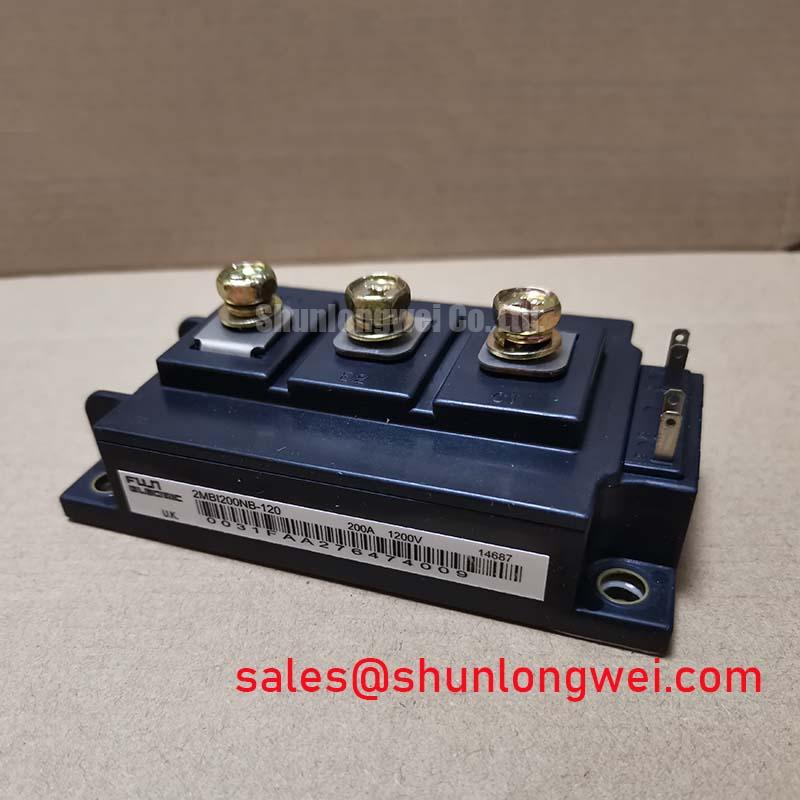
Engineered for reduced system losses, the Fuji Electric 2MBI200NB-120-01 is a dual IGBT module utilizing advanced N-Series trench gate and field-stop technology. Key Specifications: 1200V | 200A | VCE(sat) 2.2V typ. This design delivers superior switching performance and a low collector-emitter saturation voltage. For engineers optimizing high-frequency power converters, the key benefit is a direct reduction in both conduction and switching losses, leading to higher overall system efficiency. This module's characteristics answer the critical question of how to minimize thermal overhead in compact inverter designs.
A Closer Look at Key Performance Parameters
The technical specifications of the 2MBI200NB-120-01 are foundational to its performance in demanding power conversion systems. Adhering to the manufacturer's official documentation, the following parameters are critical for design and integration.
| Parameter | Symbol | Condition | Value |
|---|---|---|---|
| Collector-Emitter Voltage | VCES | VGE = 0V | 1200 V |
| Continuous Collector Current | IC | TC = 80°C | 200 A |
| Collector-Emitter Saturation Voltage | VCE(sat) | IC = 200A, VGE = 15V | 2.2 V (Typ.), 2.8 V (Max.) |
| Turn-on Switching Loss | Eon | VCC=600V, IC=200A, VGE=±15V, RG=5.6Ω | 25 mJ/pulse |
| Turn-off Switching Loss | Eoff | 26 mJ/pulse | |
| Thermal Resistance (Junction to Case) | Rth(j-c) | IGBT per 1/2 Module | 0.16 °C/W |
For more detailed specifications, please refer to the official 2MBI200NB-120-01 Datasheet.
Technical Analysis: Unpacking Switching Efficiency
The core of the 2MBI200NB-120-01's value lies in its N-Series chip technology, which is specifically engineered to balance conduction and switching losses. The typical VCE(sat) of 2.2V at its nominal current rating is a significant factor. Think of VCE(sat) as the "toll" the current pays to pass through the switch when it's on; a lower toll means less energy is wasted as heat during the on-state. This directly contributes to lower conduction losses, a critical factor in applications with high duty cycles.
Equally important are the switching energy values (Eon and Eoff). What is the primary benefit of its low switching energy? Reduced heat generation during the on/off transitions. This is especially vital in systems operating at higher frequencies, such as modern Variable Frequency Drives (VFDs). Lower total switching losses (Ets) allow for either an increase in operating frequency for better motor control and smaller magnetics, or a reduction in the required heatsink size, saving cost and space.
Application Value in High-Frequency Systems
The performance characteristics of the Fuji Electric 2MBI200NB-120-01 make it a strong candidate for power conversion systems where efficiency is a primary design driver. Its ability to minimize energy losses translates directly into reduced operating costs and improved system reliability through lower component temperatures.
- Industrial Motor Drives: In VFDs and servo drives, the module's low VCE(sat) and fast switching capabilities enable precise motor control while minimizing the heat dissipated in the power cabinet, a crucial aspect of system longevity.
- Solar and Wind Inverters: For renewable energy systems, maximizing the conversion efficiency from DC to AC is paramount. The reduced losses of this module ensure that more of the generated power is delivered to the grid. For systems requiring a different configuration, the BSM200GB120DN2 offers an alternative topology.
- Uninterruptible Power Supplies (UPS): The efficiency of the 2MBI200NB-120-01 is beneficial for high-power UPS systems, reducing cooling requirements and improving the total cost of ownership (TCO) over the system's lifetime.
For high-frequency applications where minimizing total power loss is the primary engineering goal, the 2MBI200NB-120-01's balance of low VCE(sat) and switching energy makes it a highly effective choice.
Strategic Advantage Through Advanced Silicon Technology
Integrating modules like the 2MBI200NB-120-01 reflects a strategic move towards more energy-efficient power systems. As regulations surrounding energy consumption become more stringent and the demand for higher power density grows, the selection of components with optimized loss characteristics is no longer just a performance goal—it is a competitive necessity. The N-series technology from Fuji Electric is a direct response to this trend. By leveraging advanced silicon designs, such as trench gate structures, engineers can develop systems that meet next-generation efficiency standards. This forward-looking approach to component selection helps future-proof designs against evolving performance expectations and regulatory landscapes. For more insights on IGBT fundamentals, explore our guide on IGBT structure and technology.
Frequently Asked Questions (FAQ)
1. What is the main advantage of the N-Series technology used in the 2MBI200NB-120-01?
The primary advantage is the optimized trade-off between collector-emitter saturation voltage (VCE(sat)) and switching speed. This results in lower overall power losses (both conduction and switching), which improves the efficiency and reduces the thermal load in the end application.
2. Can this module be used in parallel for higher current applications?
Yes, IGBT modules like the 2MBI200NB-120-01 can typically be paralleled. However, successful paralleling requires careful attention to the gate drive circuit design, busbar layout to ensure symmetrical current sharing, and thermal management. The positive temperature coefficient of VCE(sat) helps in balancing current, but a robust engineering approach is essential. For further reading, our article on robust IGBT gate drive design offers practical tips.
3. What does the "NB" in the part number signify?
In Fuji Electric's part numbering system, "NB" typically refers to their N-Series of IGBTs. This series is known for its trench gate and field-stop structure, which provides the favorable balance of low losses and fast switching discussed earlier.
4. How does the thermal resistance of 0.16 °C/W impact my design?
This value indicates a relatively efficient heat transfer path from the IGBT junction to the module's case. A lower thermal resistance means the generated heat can be more easily extracted by the heatsink. This is critical for maintaining the junction temperature within safe operating limits, directly influencing the module's reliability and lifespan under load.