Content last revised on September 22, 2026
Field Diagnostics and Commissioning: Atmospheric Neutron Radiation Considerations for 2MBI200U2A-060 Topologies
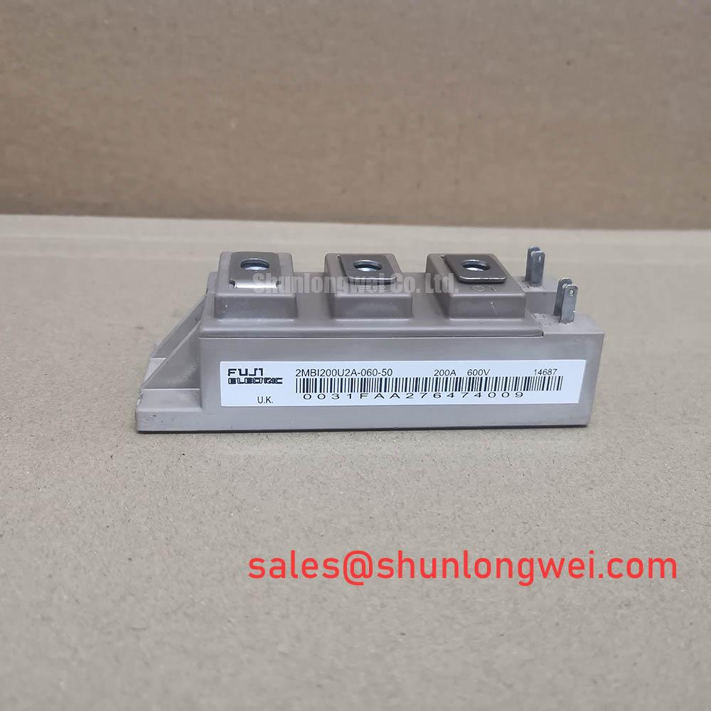
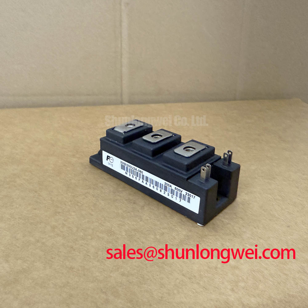
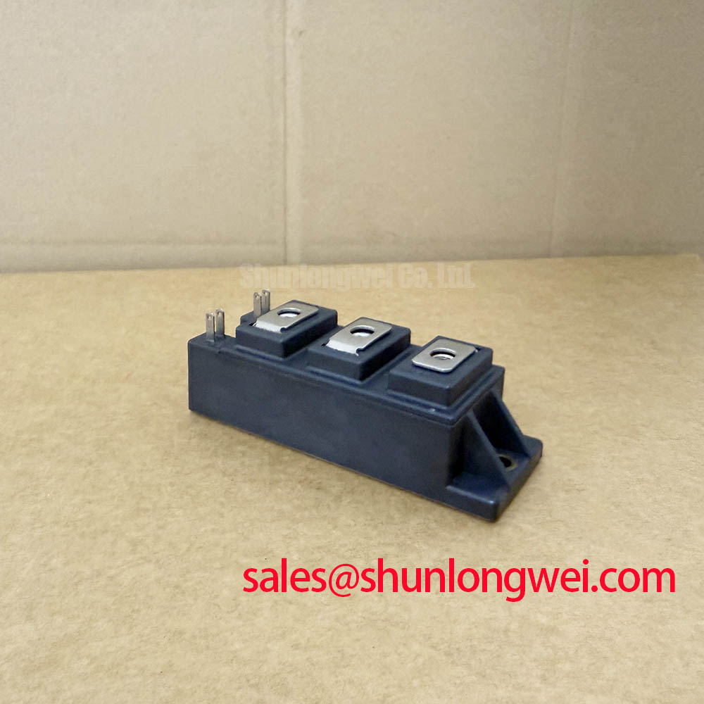
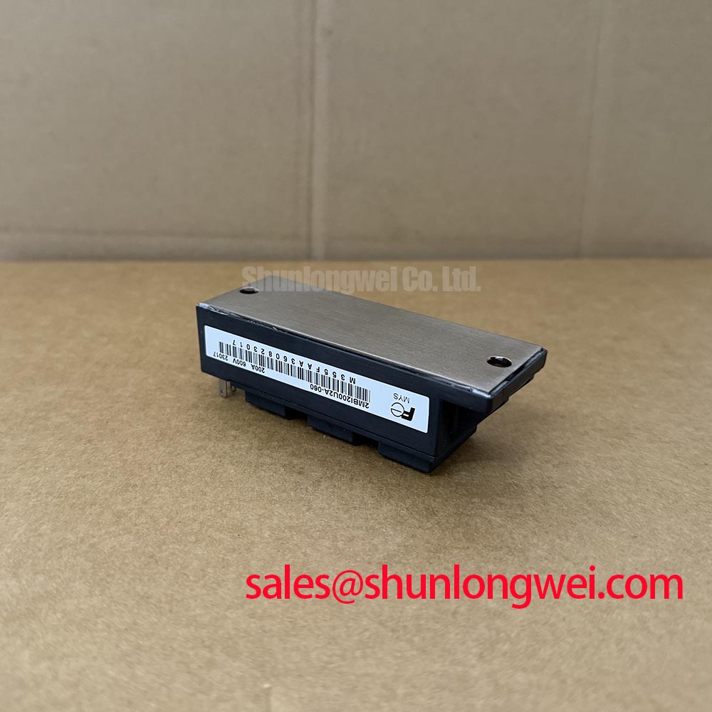
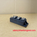
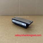
With the DC link discharged and the gate-drive harness isolated, verify the nameplate identity of 2MBI200U2A-060 before reconnecting a heavy-duty variable-frequency AC motor drive. This Fuji Electric power semiconductor is an IGBT Module rated at 600V and 200A, both Official Datasheet Specifications supplied for this model. Confirm that the installed circuit, bus-voltage operating range, cooling assembly, gate-drive interface, and protection arrangement are appropriate for this device before commissioning.
| Parameter | Specified Value | Classification |
|---|---|---|
| Manufacturer | Fuji Electric | Product identification |
| Part number | 2MBI200U2A-060 | Product identification |
| Collector-emitter voltage rating | 600V | Official Specification |
| Rated current | 200A | Official Specification |
| Package | Module | Official Specification |
Start commissioning by comparing the actual DC-bus operating envelope with the module's 600V collector-emitter voltage rating. This check is especially important after a drive has been moved, rebuilt, or operated at a new site. Measure the DC link under the operating conditions that create the highest voltage stress, including line variation, regenerative deceleration, and switching transients. A nominal bus reading alone does not establish peak voltage margin.
Atmospheric neutron exposure and single-event burnout are high-risk reliability subjects. No FIT rate, altitude derating value, single-event burnout probability, or operating-life figure is stated here because none is provided in the supplied official specifications for 2MBI200U2A-060. At elevated locations, including sites above 2000 m, this should be treated as a Design Consideration, not as a quantified property of this module. The drive manufacturer or responsible system engineer should determine whether the operating environment requires a documented semiconductor reliability assessment.
For field troubleshooting, separate recurring power-stage failures from control, cooling, and installation causes before attributing an event to environmental exposure. Record the DC-link waveform at a suitably rated measurement point, gate command behavior, protection-event history, heatsink condition, and load sequence leading to the trip. A fault appearing only during fast deceleration may indicate that regenerative energy handling needs investigation; a fault appearing during high-load motoring can also involve cooling degradation, gate-drive timing, cable-related transients, or a damaged connected motor.
Minimize the commutation-loop inductance to suppress turn-off inductive overshoot, then verify peak electrical stress during switching tests against the DC-link voltage and the module's rated limits. Routing, busbar geometry, capacitor placement, probe connection method, and control-ground arrangement are system-dependent. They must be reviewed on the installed drive rather than inferred from the module voltage rating alone.
For a broader discussion of power semiconductor operating principles and failure mechanisms, consult The Ultimate IGBT Knowledge Base. It is useful background when documenting a repair investigation, but it does not replace the original drive schematic, protection settings, or qualification records.
Preventing Spurious Faults: Dynamic Braking Chopper Operation Guidelines for 2MBI200U2A-060
When a heavy-duty variable-frequency AC motor drive decelerates a high-inertia load, mechanical energy can return through the inverter into the DC link. The braking chopper and ballast resistor are system-level parts that control this energy path. Their electrical ratings, thermal capacity, duty cycle, and enclosure heat rejection must be verified from the original drive design. The 600V, 200A ratings of 2MBI200U2A-060 identify the module's published electrical class; they do not define a braking-resistor value, chopper current limit, or regenerative-energy capacity.
A drive that trips during deceleration should be examined with attention to the braking command, DC-link rise, chopper switching behavior, resistor continuity, resistor thermal protection, and associated wiring. Do not assume that a DC overvoltage event has one cause. A resistor with altered resistance, a failed control signal, loose power connections, insufficient cooling, parameter changes, or an external load condition can each affect braking performance. Compare measurements with a known-good drive where available and follow the machine builder's service documentation.
⚠️ Maintenance Note: Periodically monitor terminal contact temperature and confirm that the cooling airflow path remains clear before repeated high-load operation.
Bootstrap supply integrity is also a Design Consideration for inverter gate-drive systems that use a floating high-side supply. The required capacitance depends on the actual driver quiescent current, gate charge, switching duty, refresh interval, leakage paths, supply-voltage tolerance, and permitted ripple. The system engineer should calculate the requirement from the selected driver documentation and validate gate-emitter voltage at the module terminals throughout the operating sequence. No gate-charge value or bootstrap-capacitor value is asserted for this model because neither is among the supplied official parameters.
Gate-loop disturbance can create false protection events or irregular switching. Inspect the driver supply rails, isolation barrier where fitted, gate-return routing, and controller ground reference with appropriate instruments. A negative gate bias, active clamp arrangement, or other gate-control method must only be used where supported by the specific module and driver documentation. Verify the entire installed topology rather than applying a generic gate-drive value to this module.
Where the upstream conversion stage is under review, 2MBI200UB-120 can be assessed as a separately listed module for related power-conversion requirements. Electrical topology, voltage class, thermal behavior, terminal arrangement, and drive compatibility require independent verification before any service decision.
Preventing Spurious Faults: Baseplate Convexity Compensation and Screw Guidelines for 2MBI200U2A-060
Before mounting 2MBI200U2A-060, inspect the heatsink contact face for corrosion, embedded debris, scratches, old thermal compound, and local distortion. Clean the mating surfaces using a method compatible with the equipment maintenance procedure, then inspect the module exterior for handling damage. The module is specified as a Module; mounting-hole size, thread size, baseplate flatness, and manufacturer torque values are not included in the supplied specifications and should be confirmed from the original equipment documentation.
Thermal interface material is used to fill unavoidable microscopic surface variation between a power module and its heatsink. As a general industry Design Consideration, technicians commonly control a thermal compound layer within approximately 50 to 100 micrometres where the selected material and assembly method support that range. This is not an official thickness specification for 2MBI200U2A-060. The correct application quantity depends on the actual heatsink finish, interface material, clamping pattern, and mechanical tolerances.
Baseplate curvature and heatsink flatness must be treated as a contact-pressure problem. Excessive compound can increase thermal resistance, while incomplete coverage can leave localized contact loss. Apply thermal material consistently, position the module without sliding it through accumulated debris, and tighten fasteners progressively in a balanced sequence. The final tightening torque must come from the module documentation and the drive manufacturer's mechanical instructions. A generic torque value should not be substituted for a product-specific requirement.
After reassembly, check whether the heatsink fan, ducting, filters, and cabinet ventilation restore the intended thermal path. In environments subject to temperature cycling, moisture, dust, or condensation, inspect for corrosion at terminals and mounting interfaces during planned maintenance. A rising temperature trend may indicate an assembly, airflow, loading, or control issue and should be investigated with measured operating data rather than judged by cabinet appearance alone.
For repair planning, the linked 2MBI200UR-120-01 is a separately listed power module that may be reviewed alongside the failed-device requirements. It is not presented as an automatic replacement. Engineers should verify circuit topology, voltage rating, current requirements, terminal layout, gate-drive conditions, mechanical fit, and protection coordination against the original equipment.
Assembly Integrity and Layout Architecture: High-Speed Fault Management for 2MBI200U2A-060
Verify the protective path before applying power: the controller must recognize an abnormal collector-emitter condition, command a controlled response, and record the event for service analysis where the drive architecture provides that capability. Desaturation detection is commonly used in IGBT gate-drive systems to observe a rising collector-emitter voltage during a commanded on-state. The threshold, blanking interval, sensing network, and response sequence belong to the installed gate driver and system design; no desaturation threshold or short-circuit withstand time is claimed for 2MBI200U2A-060 from the supplied data.
Short-circuit protection timing is critical because an IGBT can experience high simultaneous voltage and current stress. The designer should validate the protection response against the module's applicable manufacturer documentation, the actual DC link, temperature, gate conditions, and measured stray inductance. A controlled soft turn-off can limit the rate of current interruption and reduce inductive overvoltage during a fault, but its effectiveness depends on the gate driver, power-loop layout, clamping arrangement, and switching conditions. It must be proven on the completed equipment using safe test methods.
During troubleshooting, inspect desaturation sense wiring for contamination, damaged insulation, poor solder joints, and routing that exposes the signal to high-current switching loops. Check that the gate driver has its intended local supply and that the controller reacts consistently to an injected or documented protection test where the equipment procedure permits. Spurious desaturation alarms may indicate a sensing-path issue, a ground-reference disturbance, switching noise, or a genuine power-stage abnormality. Oscilloscope comparison with a validated channel can help distinguish these possibilities.
Keep gate-drive loops compact and keep fault-sense paths away from high-current commutation paths to improve measurement integrity. Verify peak collector-emitter voltage, gate-emitter voltage, and protection sequence during representative switching conditions. Fuji Electric's published Brake Chopper IGBT Modules information and its 7th-Gen X-Series IGBT Modules resources provide manufacturer context for IGBT module product families. They should be used alongside the exact documentation applicable to the installed 2MBI200U2A-060 assembly.