Content last revised on April 27, 2026
Fuji Electric 6MBI100UB-120: Engineering Efficiency in 6-in-1 Power Topologies
Executive Overview & Core Specifications
Driving Next-Generation Motor Control Systems
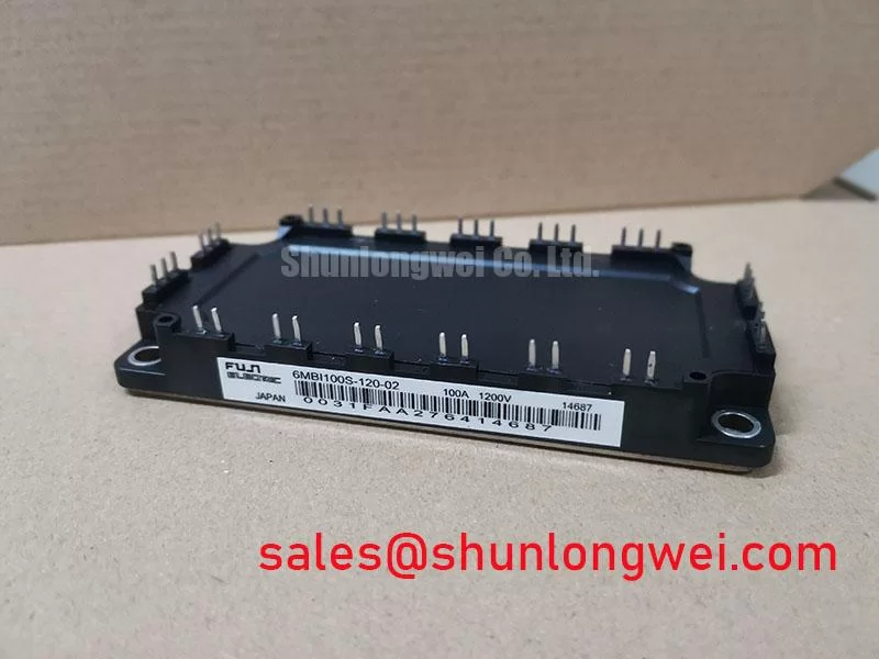
In the demanding landscape of power electronics, optimizing both layout architecture and switching performance is a continuous engineering challenge. The Fuji Electric 6MBI100UB-120 is a highly integrated 1200V, 100A 6-in-1 IGBT module engineered to maximize switching efficiency and simplify thermal management in three-phase motor drives. By housing all six power switches within a single baseplate, it fundamentally resolves the layout complexities associated with discrete components. What is the key advantage of a 6-in-1 IGBT configuration? It drastically reduces parasitic inductance by keeping current loops short. Key specifications include a robust 1200V blocking capability, 100A nominal current, and an optimized U-Series trench gate structure. These elements converge to minimize PCB layout complexity while dramatically lowering overall conduction losses. For 480V AC variable frequency drives prioritizing compact layout and thermal margin, this 1200V module is the optimal choice.
Key Parameter Overview
Decoding the Specs for Enhanced Thermal Reliability
To accelerate your IGBT module selection, the critical specifications of the 6MBI100UB-120 are functionally grouped below to highlight its system-level capabilities.
| Category | Parameter | Value / Condition |
|---|---|---|
| Maximum Ratings | Collector-Emitter Voltage (Vces) | 1200V |
| Maximum Ratings | Continuous Collector Current (Ic) | 100A (Tc = 80°C) |
| Electrical Specs | Collector-Emitter Saturation Voltage Vce(sat) | Optimized for low conduction loss |
| Package / Thermal | Module Configuration | 6-in-1 (Hex) Three-Phase Bridge |
| Package / Thermal | Isolation Voltage (Visol) | 2500V AC (1 minute) |
Download the 6MBI100UB-120 datasheet for detailed specifications and performance curves.
Application Scenarios & Value
Achieving System-Level Benefits in Industrial Inverters
Engineers designing the power stage for a Variable Frequency Drive (VFD) frequently face the dual challenges of managing stringent space constraints and mitigating destructive switching spikes. In a typical 480V AC grid application, the physical layout of the three-phase bridge dictates the entire system's susceptibility to electromagnetic interference (EMI) and transient overvoltages.
The 6MBI100UB-120 provides an elegant, hardware-level solution. Its 6-in-1 integration tightly couples the upper and lower arms of all three phases internally. This architectural choice reduces the physical distance between connections, effectively minimizing the stray inductance that causes dangerous voltage overshoots during high-frequency PWM switching. Consequently, designers can utilize smaller snubber circuits, conserving valuable board space and streamlining the bill of materials. While the 6MBI100UB-120 is optimal for 100A power stages, systems demanding higher current capacity can smoothly transition to the complementary 6MBI150U4B-120-50 for expanded power delivery.
Technical Deep Dive
The Physics of U-Series Silicon and Hex-Integration
The electrical foundation of the 6MBI100UB-120 relies on Fuji Electric's proven U-Series silicon, which balances conduction and switching losses for mid-frequency industrial applications. However, the true engineering triumph that drives system efficiency lies in its hex-package execution.
Think of parasitic inductance in a power inverter like water hammer in industrial plumbing; the sudden stopping of rapid flow (current) causes destructive pressure spikes (voltage spikes). The highly integrated 6-pack design acts as a built-in shock absorber by keeping the current commutation loops incredibly short, safely clamping these transient spikes during dynamic operation. This allows for more aggressive gate drive tuning without risking semiconductor failure.
Furthermore, thermal distribution is radically simplified. Managing heat in separate discrete IGBTs is akin to trying to cool six different small ovens with separate, uncoordinated fans. Conversely, the 6MBI100UB-120 baseplate combines all six switches into a single, highly uniform thermal plane. This makes heatsink coupling far more predictable, preventing localized hotspots and ensuring long-term reliability even under heavy cyclic motor loads. Elevate your system's robustness by integrating this unified power topology into your next project.
Frequently Asked Questions
Resolving Common Engineering Inquiries
- How does the 6-in-1 configuration of the 6MBI100UB-120 directly impact overvoltage spikes during switching?
By housing the entire three-phase bridge within a single module, the internal DC bus connections are mathematically optimized, drastically lowering stray inductance compared to discrete point-to-point wiring. This minimizes the inductive voltage overshoot, allowing for safer high-speed switching and relaxed external snubber requirements. Request pricing now to leverage these design efficiencies. - What makes the 1200V / 100A rating ideal for industrial motor control?
A 1200V blocking voltage provides the necessary safety margin for operating reliably on a standard 400V or 480V AC line, effortlessly absorbing industrial grid fluctuations. Simultaneously, the 100A continuous current capability ensures sufficient torque generation and overload capacity for mid-range industrial motors without the need for complex, space-consuming paralleling schemes.