


Content last revised on May 26, 2026
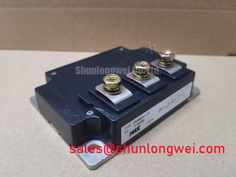
CM100E3Y-24E: 1200V/100A Single IGBT Module Engineered for Low-Loss Power Conversion
Introduction: A Focus on Conduction Loss Reduction
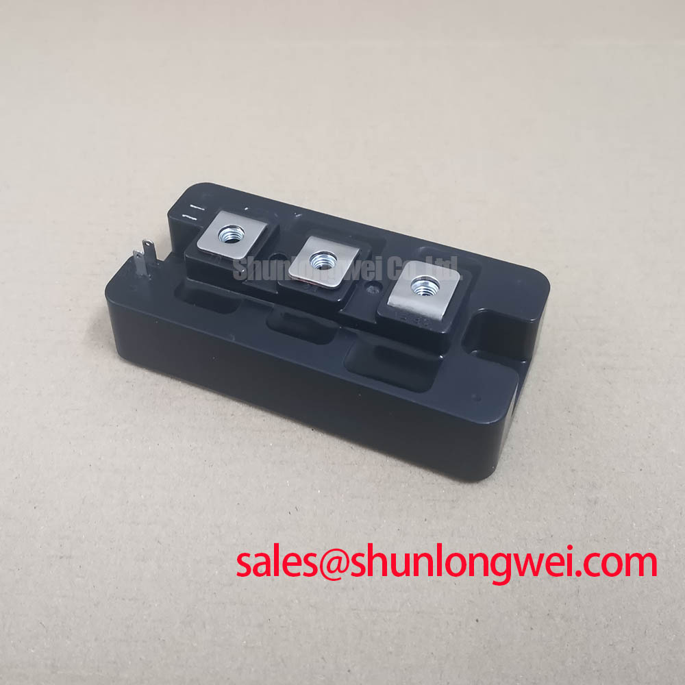
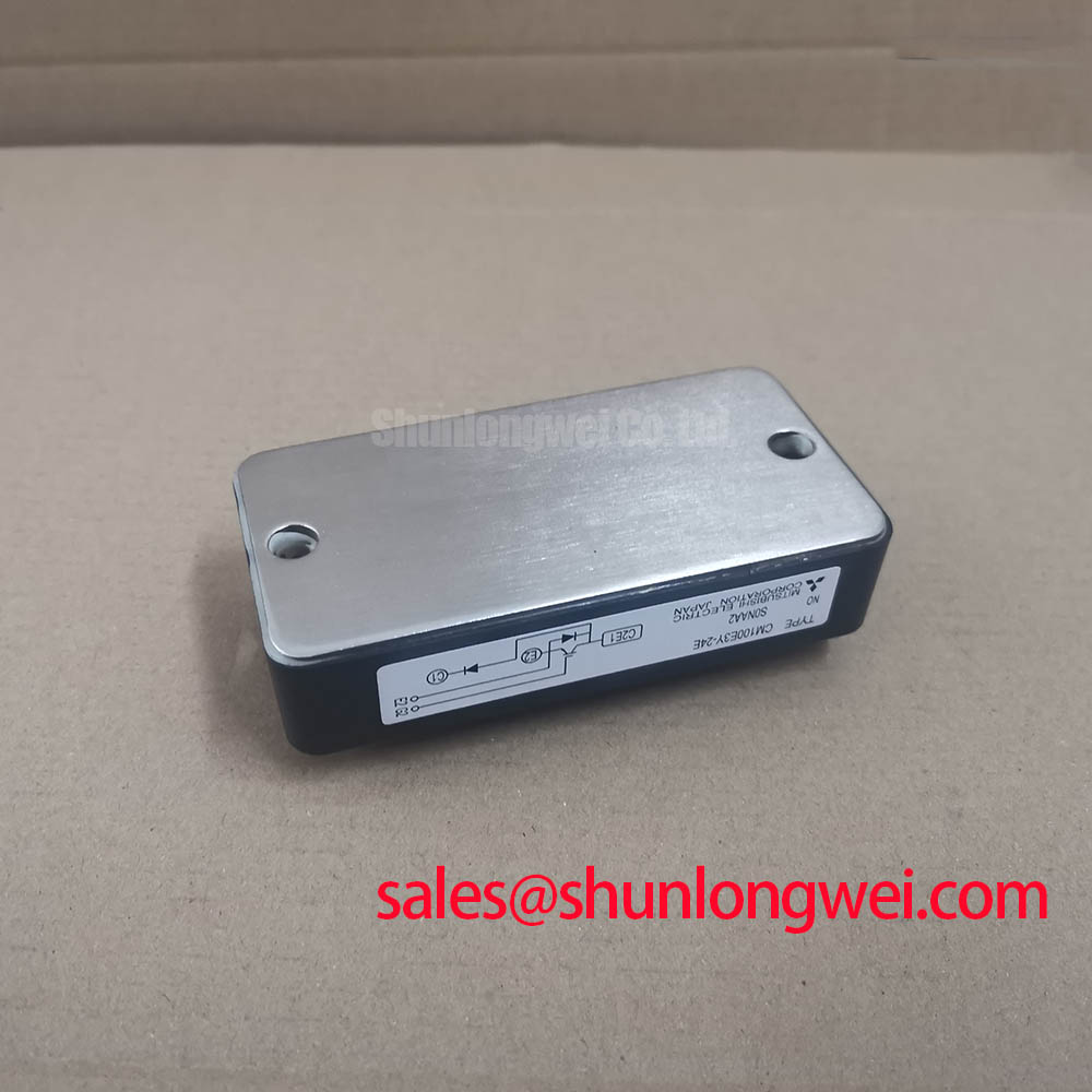
The Powerex CM100E3Y-24E is a high-performance single IGBT module engineered to minimize conduction losses, enabling superior efficiency and thermal headroom in demanding power conversion systems. It integrates Mitsubishi's 6th Generation CSTBT™ technology to deliver benchmark performance. Key specifications include: 1200V | 100A | VCE(sat) 2.1V (typ). This translates directly into two primary engineering benefits: superior energy efficiency and simplified thermal management. The module's single-switch configuration provides the flexibility required for custom topologies like high-power chopper circuits or individual inverter legs. What is the primary benefit of the CM100E3Y-24E's low VCE(sat)? Reduced conduction losses leading to higher system efficiency. This module is best suited for medium-frequency (5-20 kHz) power converters where minimizing conduction losses is the primary design driver.
Application Scenarios & Value
System-Level Gains from Optimized Conduction and Switching Performance
The CM100E3Y-24E is designed for industrial applications where efficiency and reliability are paramount. Its robust electrical characteristics make it an excellent choice for systems such as:
- High-power UPS (Uninterruptible Power Supply) systems
- Industrial motor and Servo Drive controls
- Welding power supplies and induction heating equipment
- Boost, buck, or chopper circuits for renewable energy and power management
Consider the engineering challenge of a high-power UPS. In this scenario, every watt of energy lost as heat not only reduces overall efficiency but also increases the thermal load within the enclosure, potentially requiring larger, more costly cooling systems. The CM100E3Y-24E directly addresses this challenge with its low collector-emitter saturation voltage (VCE(sat)). Think of VCE(sat) as the "energy toll" the current pays to flow through the device when it's on. With a typical VCE(sat) of just 2.1V at its rated 100A current, this module exacts a very low toll, significantly cutting down on conduction losses (P = VCE(sat) * Ic). This reduction in waste heat allows designers to achieve higher power density, improve system reliability, and lower the total cost of ownership. For systems requiring higher current handling within a similar voltage class, the CM150DY-24H offers a 150A rating.
Key Parameter Overview
Decoding the Electrical and Thermal Specifications for Efficient Design
The technical specifications of the CM100E3Y-24E are foundational to its performance. The parameters below are organized to assist engineers in system modeling and component selection.
| Parameter | Symbol | Conditions | Value |
|---|---|---|---|
| Absolute Maximum Ratings (Tj = 25°C unless otherwise specified) | |||
| Collector-Emitter Voltage | VCES | - | 1200V |
| Gate-Emitter Voltage | VGES | - | ±20V |
| Collector Current (DC, TC=25°C) | IC | - | 100A |
| Collector Current (Pulse) | ICM | - | 200A |
| Maximum Power Dissipation (TC=25°C) | PC | - | 520W |
| Electrical Characteristics (Tj = 25°C unless otherwise specified) | |||
| Collector-Emitter Saturation Voltage | VCE(sat) | Ic = 100A, VGE = 15V, Tj=125°C | 2.1V (Typ), 2.7V (Max) |
| Gate-Emitter Leakage Current | IGES | VGE = ±20V | 500nA |
| Collector-Emitter Cutoff Current | ICES | VCE = 1200V | 1mA |
| Short Circuit Withstand Time | tsc | VCC ≤ 600V, VGE = 15V, Tj=125°C | 10µs (Min) |
| Thermal & Mechanical Characteristics | |||
| Thermal Resistance (Junction to Case, IGBT) | Rth(j-c) | - | 0.24 °C/W |
| Thermal Resistance (Junction to Case, Diode) | Rth(j-c) | - | 0.43 °C/W |
| Operating Junction Temperature | Tj | - | -40 to 150°C |
Frequently Asked Questions (FAQ)
Engineering Questions on the CM100E3Y-24E's Performance
How does the 2.1V typical VCE(sat) of the CM100E3Y-24E influence the thermal design of a power converter?
A lower VCE(sat) directly reduces the power lost as heat during the conduction phase (P_cond = VCE(sat) × I_c). This lower heat generation means a smaller, lighter, and more cost-effective heatsink can be used to maintain the junction temperature within safe operating limits. It's a critical factor for improving the power density and reliability of the end system. For a deeper dive into this topic, explore this guide on unlocking IGBT thermal performance.
What is the significance of the 6th Generation CSTBT™ technology in this module?
CSTBT™ (Carrier Stored Trench-Gate Bipolar Transistor) is a proprietary technology that optimizes the trade-off between conduction losses (VCE(sat)) and switching losses. The 6th generation refines this balance, enabling both a low VCE(sat) for high efficiency at medium frequencies and soft switching characteristics that can help reduce electromagnetic interference (EMI), simplifying filter design.
What design considerations are important for the gate drive circuit given the module's specifications?
The datasheet specifies key parameters like total gate charge (Qg) and input capacitance (Cies) which dictate the drive current required for fast, efficient switching. A robust gate drive design must provide sufficient peak current to charge and discharge this capacitance quickly, minimizing switching losses. Additionally, using the recommended gate-emitter voltage (typically +15V for turn-on, -5V to -15V for turn-off) is crucial for ensuring full enhancement and preventing unintended turn-on events.
Technical Deep Dive
Inside the 6th Gen CSTBT™: A Closer Look at the Technology Driving Low VCE(sat)
The performance of the CM100E3Y-24E is fundamentally rooted in its 6th generation CSTBT™ silicon. This technology employs a unique trench gate structure combined with a carrier-storage layer. This design allows for a higher concentration of charge carriers in the "on" state, which effectively lowers the resistance of the device and results in the exceptionally low VCE(sat). What technology does the CM100E3Y-24E use? It utilizes Mitsubishi's 6th Generation CSTBT™ technology.
A key parameter for evaluating the effectiveness of thermal design is the junction-to-case thermal resistance, Rth(j-c). For the CM100E3Y-24E, this is specified at 0.24 °C/W. This value can be understood as the "insulation" between the heat-generating silicon chip and the module's baseplate. A lower Rth(j-c) value is like having very thin, highly conductive insulation, allowing heat to escape quickly and efficiently to the heatsink. This efficiency in heat transfer is vital for maintaining reliability under heavy loads and preventing the device from exceeding its maximum junction temperature.
Your Next Step
To evaluate if the CM100E3Y-24E meets the specific demands of your power system, we recommend a thorough review of the official datasheet. It provides comprehensive performance curves and detailed specifications necessary for accurate design simulations and thermal modeling.