
Content last revised on October 3, 2026
PM150DSA120 Operational Boundaries: Evaluating Hard Switching Transients
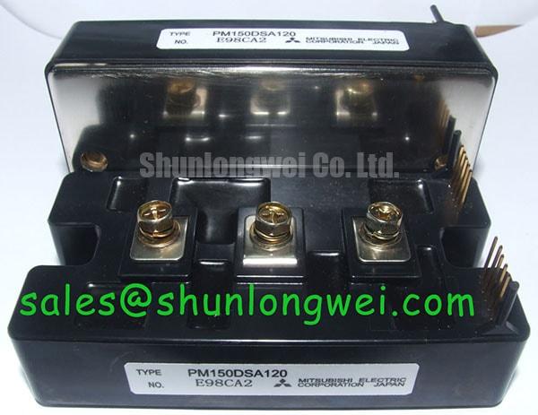
Before energizing a replacement, inspect the PM150DSA120 housing for mechanical damage, confirm the nameplate identity, and verify that the original control circuit is designed for a 1200 V, 150 A Mitsubishi Electric IPM module. The listed package category is Mitsubishi IPM Module. These are the product-level parameters available for this page; control timing, protection thresholds, thermal curves, pin assignments, and switching limits must be checked against the applicable Mitsubishi Electric documentation for the exact hardware revision.
| Parameter | Specification | Classification |
|---|---|---|
| Product model | PM150DSA120 | Product identification |
| Manufacturer | Mitsubishi Electric | Product identification |
| Rated voltage | 1200 V | Device rating |
| Rated current | 150 A | Device rating; applicable conditions must be checked |
| Package | Mitsubishi IPM Module | Product category |
The 1200 V rating should be treated as an electrical boundary, not as a target operating point for an uncontrolled switching waveform. In a traction inverter, the DC link, busbar geometry, cable inductance, internal switching behavior, load current, and commutation path all influence the voltage that appears across the module during turn off. Designers should measure the actual collector-emitter waveform at the module terminals and compare the observed peak with the system voltage margin required by the validated design.
Short-circuit protection requires particular care because an IPM protection function is part of a complete control system rather than a substitute for system-level fault management. Evaluation of Type I and Type II short-circuit behavior should begin with the applicable Mitsubishi Electric protection documentation, including the specified detection behavior, fault output behavior, and safe operating limits. Do not assume that a response time quoted for another Mitsubishi module applies to the PM150DSA120.
Fault shutdown behavior can affect the voltage generated by stored inductive energy in the switching loop. The PM150DSA120’s internal turn-off behavior should be assessed from its documentation and validated in the intended circuit; an external two-stage gate turn-off strategy should not be assumed to be available. Busbar layout, snubbing, control timing, and fault handling are system-level considerations that require bench validation with suitable high-voltage and isolated current measurement methods.
For an industrial electric forklift or material-handling traction controller, troubleshooting should separate a genuine semiconductor fault from a control, busbar, braking, or load problem. With power removed and the DC link safely discharged, inspect the module mounting surface, terminal connections, snubber path, control wiring, and fault feedback wiring. A static resistance result alone is not sufficient to approve a module. Compare the suspect phase with a known-good phase, then perform controlled functional testing according to the applicable module documentation before applying full bus voltage.
Keep the commutation loop physically compact and symmetrical, with the high-current path separated from sensitive control and fault signal wiring. Clearance and creepage distances must be selected from the working voltage, pollution environment, insulation system, and applicable equipment standard. The module itself should not be described as independently compliant with an equipment EMC or safety certification; final compliance belongs to the complete traction controller.
Mitsubishi Electric application information on related power device topologies can provide useful background when reviewing switching and bootstrap arrangements. The Mitsubishi DIPIPM Bootstrap Circuit Design document should be treated as application guidance, not as a replacement for the PM150DSA120 data applicable to the installed circuit.
PM150DSA120 Thermal Electrical Optimization: Control Wiring and Layout Symmetry
The PM150DSA120 combines a high-voltage rating with a 150 A current rating, but the usable operating point depends on switching loss, conduction loss, case temperature, heat sink performance, airflow, duty cycle, and fault repetition. The current rating should therefore be read under its specified conditions rather than as a promise of continuous operation at every switching frequency or ambient condition.
A practical layout review begins at the controller connector and follows the control inputs, supply connections, and reference paths to the module. Sensitive control and fault wiring should not share an uncontrolled section of the main high-current path. Shared impedance can convert power-current changes into disturbances on control signals, causing unreliable switching commands or fault indications. The exact terminal arrangement must be confirmed from the relevant mechanical and electrical drawing before the board is released.
Control-wiring symmetry matters when the module is used in a three-phase traction inverter. Keep signal paths and their returns close together, avoid unnecessary routing around power terminals, and follow the manufacturer’s recommendations for input filtering and connections. Designers should examine switching waveforms at the module power terminals rather than relying only on a control signal measurement taken at the control board.
Thermal evaluation across a proposed switching range should use measured loss data, not a generic frequency rule. A design operating near 2 kHz may have a different balance between conduction and switching loss from one operating near 16 kHz, but the PM150DSA120 data sheet limits and the actual modulation profile determine whether either condition is acceptable. Heat sink flatness, interface material application, clamping force, enclosure airflow, blocked filters, and fan aging all need to be included in the thermal test plan.
When a repaired controller shows intermittent overcurrent or thermal alarms, inspect the complete cooling path before replacing the module again. Check the heat sink contact pattern, fastening sequence, fan command, airflow direction, and temperature sensor attachment. A temperature increase can also be caused by abnormal commutation or control timing, so correlate thermal measurements with phase current and switching waveforms.
💡 Pro Tip: Disconnect the DC link and wait for verified discharge before removing control or power connectors, because residual energy and an uncontrolled connector sequence can damage both the module and its control circuitry.
For purchasing and engineering review, the SKIIP37AC12T4V1 page may be consulted as a separate module reference during a documented replacement assessment. Mechanical fit, voltage class, current behavior, control interface, protection logic, and thermal data must be matched individually; a similar package description does not establish interchangeability.
Transient Dynamics and Electrical Design: Switching Transient Evaluation
High dv/dt at one switch position can couple into nearby control wiring and create unwanted signal disturbances. In a half bridge, unintended switching can produce abnormal current spikes or repeated protection events. The PM150DSA120 is an IPM, so an external active Miller clamp or direct gate connection must not be assumed to be available from the product parameters supplied here.
For that reason, the control designer should first verify the exact terminal definition and recommended input and supply conditions from the Mitsubishi Electric documentation for this module. A negative off bias between minus five volts and minus fifteen volts must not be treated as an external drive prescription for this model. The relevant design considerations are the documented control interface, isolation, supply behavior, common-mode transients, and fault response.
Control and fault-signal wiring should follow the intended reference paths while remaining physically separated from the power switching loop. During evaluation, measure the phase node, DC link, control inputs, and fault outputs as appropriate for the documented interface. If a waveform changes when the probe connection arrangement changes, the measurement setup may be influencing the result.
Field troubleshooting should compare the same switching event across all phases. Look for differences in control-signal timing, turn-off slope, ringing duration, fault-signal timing, and phase current. These observations may indicate a control-wiring problem, excessive commutation inductance, a supply issue, or a load problem. They do not prove that the module silicon is defective without additional tests.
Where switching transients are a concern, the system engineer should verify supply tolerance, start-up sequence, fault state, isolation behavior, and voltage at the module terminals under the relevant operating conditions. The appropriate corrective action is system-dependent. It should be validated with controlled switching tests while checking voltage overshoot against the DC link boundary.
The Evolution of Negative Off Bias Gate Drive Circuits guide can provide background on gate-drive arrangements used with other power devices. It does not establish an external negative gate-bias requirement or connection method for the PM150DSA120.
PM150DSA120 Operational Boundaries: Evaluating Multi-Module Parallel Current Sharing
Parallel operation should not be assumed from the 150 A rating. When multiple power modules are connected in parallel, static current sharing is influenced by conduction voltage characteristics, temperature, busbar resistance, terminal contact resistance, and the symmetry of the mechanical layout. A positive temperature coefficient of conduction voltage can support passive sharing under some operating conditions, but the complete behavior must be confirmed from the applicable electrical characteristics, manufacturer guidance, and measured current distribution.
Dynamic sharing is usually more sensitive than steady-state sharing. Each module should receive appropriately coordinated control signals and supplies, with comparable wiring and reference paths. The power busbars should also be geometrically balanced so that one module does not experience a materially different commutation inductance from another. The target is not theoretical symmetry on the CAD drawing; it is a measured balance during the fastest and highest-current switching events.
Before connecting modules in parallel, inspect the individual control channels and confirm that fault outputs are handled in a coordinated way. A fault in one channel must not leave another parallel device in an uncontrolled state. The system integrator should also verify whether the protection architecture permits independent fault detection, coordinated shutdown, or a common fault latch. These functions cannot be inferred from the product name alone.
During commissioning, begin with a controlled current level and use isolated voltage probes and matched current sensors to compare each module branch. Increase operating stress only after checking turn-on current, turn-off overshoot, control-signal integrity, and thermal response. If one branch carries more current, examine busbar geometry, contact pressure, terminal cleanliness, control timing, and sensor alignment before changing the design.
Parallel module layouts require attention to mechanical tolerances as well as electrical routing. Uneven heat sink contact or unequal thermal paths can shift conduction behavior as temperature changes. Cooling airflow should reach the relevant heat spreader area consistently, and the enclosure should be checked for recirculation or local hot spots. Any thermal derating value must come from the manufacturer data and the measured assembly condition rather than from the nominal current rating alone.
Engineers evaluating the PM150DSA120 for electric forklift or warehouse material-handling traction equipment should document the complete replacement interface: DC link voltage, phase current, control interface, fault feedback, mounting pattern, cooling method, and software reaction to protection signals. The Mitsubishi Electric high-voltage power module reference material offers broader device technology context, while the final acceptance decision must remain tied to the exact module documentation and measured system results.