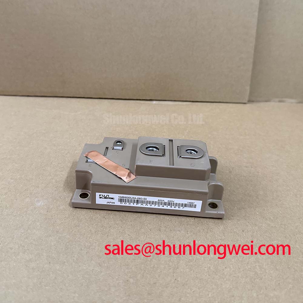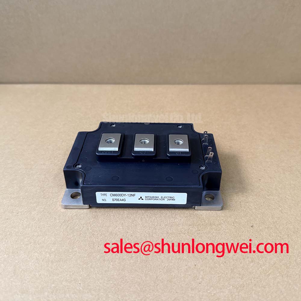
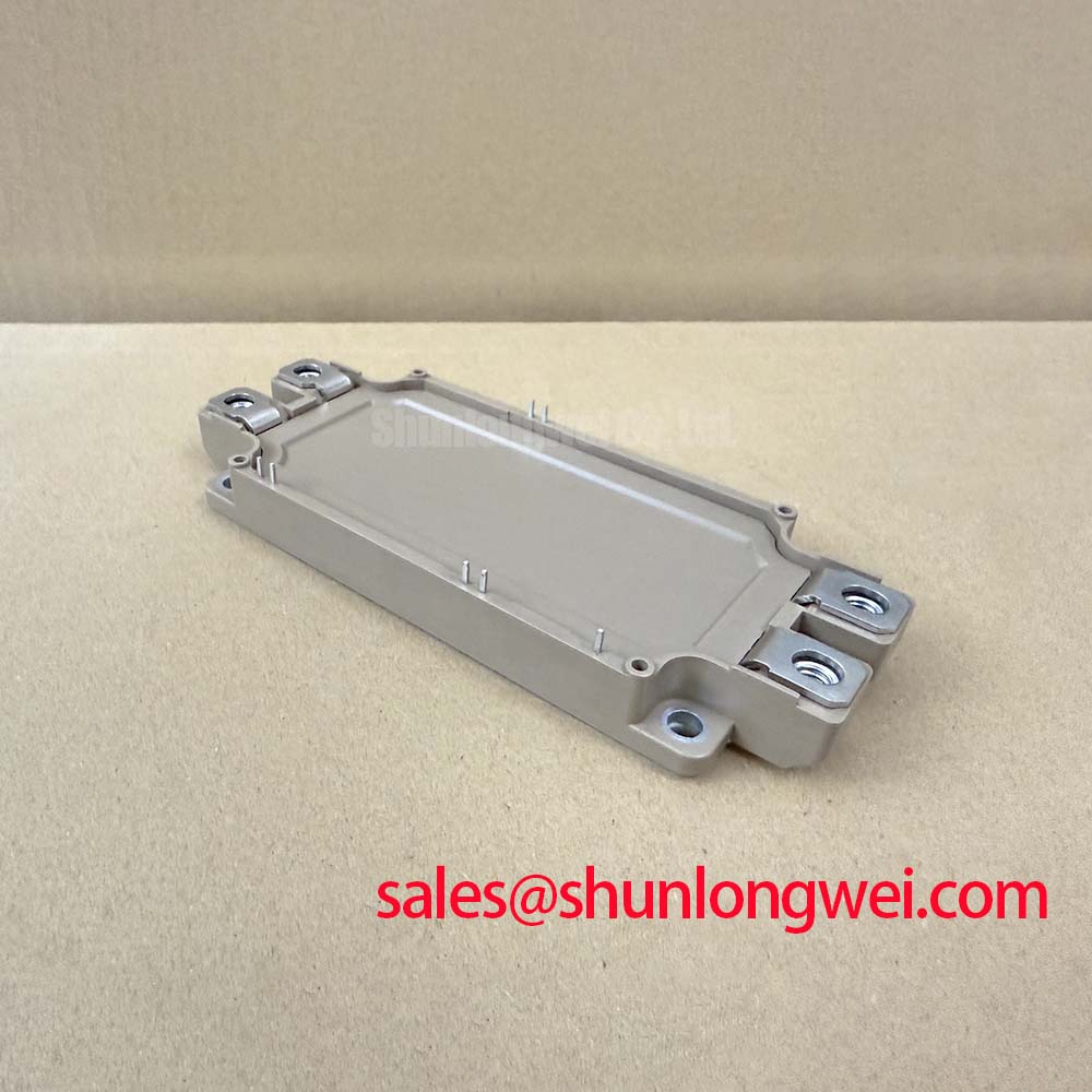





Content last revised on September 3, 2026
Before unboxing and mounting the 2MBI600VX-120-50 to a liquid cold plate or forced-air heatsink, field technicians and test engineers must execute a baseline cold impedance verification across the power terminals and auxiliary signal pins. Using a high-resolution digital multimeter in diode-check mode, verify the integrity of the internal freewheeling diodes between collector and emitter terminals across both upper and lower switches, confirming an intact junction with no latent reverse leakage. Gate-to-emitter terminals must be measured with an insulation tester or megaohmmeter configured to a low test potential to ensure the gate dielectric has suffered no electrostatic discharge (ESD) degradation during transit. Once mechanical flatness of the heatsink surface is checked against standard engineering tolerances, the module can be integrated into high-power inverter topologies where parasitic inductances and fast-switching dynamics dictate long-term system survivability.
Preventing Spurious Faults: Auxiliary Emitter Return Trace Separation Guidelines for 2MBI600VX-120-50
Fast-switching transitions within high-current power stages induce extreme rates of current change across physical circuit paths. The 2MBI600VX-120-50 dual IGBT module carries an official factory rating of VCES = 1200V and a continuous collector current rating of IC = 600A (Official Datasheet Specification). When commutating several hundred amperes within nanosecond switching intervals, any parasitic inductance present in the emitter path produces an inductive back-EMF proportional to the rate of current change over time. If the gate driver reference return is connected into the main high-current emitter power bus, this induced voltage couples directly into the gate-emitter loop, degrading gate drive signal integrity and inducing unintended turn-on or destructive phase-leg oscillation.
To eliminate mutual inductive coupling, the physical terminal arrangement of the module provides dedicated auxiliary emitter pins separated from the high-current busbar screw terminals. The auxiliary Kelvin emitter trace must serve exclusively as the return path for the gate driver stage and must never carry load current. PCB designers must route the gate drive signal and auxiliary emitter return as a tightly coupled differential microstrip or twisted-pair arrangement directly to the driver board. By minimizing the physical loop area formed by the gate-emitter drive circuit, external magnetic field pickup generated by adjacent switching busbars is significantly suppressed.
Protection topologies such as desaturation (desat) fault detection must also reference this dedicated auxiliary emitter terminal rather than an external chassis or bus ground. During a sudden short-circuit event, the collector-emitter voltage exits saturation and rises rapidly. Referencing desat sensing directly to the auxiliary terminal prevents inductive voltage drops across external bus structures from skewing the comparator threshold. As detailed in The Ultimate IGBT Knowledge Base, precise short-circuit safe operating area (SCSOA) tracking relies on clean terminal feedback to initiate soft turn-off sequences, preventing catastrophic turn-off overshoots during dead-short clearing cycles.
2MBI600VX-120-50 Operational Boundaries: Evaluating High dv/dt Cross-Conduction Shoot-Through Limits
In high-power half-bridge configurations, complementary switching operations expose the non-conducting IGBT to severe voltage transients. When the opposing switch turns on under heavy inductive loads, the collector-emitter voltage of the complementary device swings from near-zero saturation levels to the full DC-link potential at high rates of voltage rise. This steep transition causes displacement currents to flow through the parasitic gate-collector Miller capacitance (CGC) of the off-state switch, governed by the product of capacitance and voltage slope over time.
Displacement current finding its way through the internal gate impedance and external gate driver traces creates an unwanted positive voltage rise across the gate-to-emitter terminals. If this induced voltage exceeds the internal gate threshold voltage (VGE(th)), the off-state IGBT transitions into partial conduction while the opposing switch is fully active, precipitating a dangerous cross-conduction shoot-through condition. To establish adequate design margins, gate driver stages must implement an active Miller clamp (AMC) or maintain an assertive negative off-state gate bias. Implementing a stable negative gate bias between -5V and -15V (General Industry Design Consideration) ensures the gate terminal remains clamped below threshold during sharp collector voltage rises.
💡 Pro Tip: Maintain strictly symmetrical planar DC busbar geometries and verify collector-emitter transient overshoots via double-pulse switching tests under peak operating currents, ensuring sufficient design margin below the 1200V rating without prescribing arbitrary dead-time values.
Stray loop inductance throughout the DC-link busbar directly amplifies turn-off voltage spikes. High di/dt during turn-off interacts with parasitic bus inductance, generating high-voltage peaks that superimpose upon the DC bus voltage. In accordance with engineering application data published by Fuji Electric Global Power Semiconductor Technologies, decoupling capacitors composed of low-inductance polypropylene film must be mounted directly across the DC module terminals to snub these inductive spikes and secure safe commutation within the 1200V absolute maximum boundary.
Transient Dynamics & Electrical Design: Multi-Module Parallel Current Sharing on 2MBI600VX-120-50
Scaling output power in megawatt-class converter platforms—such as central conversion systems—often necessitates paralleling multiple 2MBI600VX-120-50 power modules on a common DC bus. Uniform current sharing among paralleled devices during both static conduction states and dynamic switching transitions is paramount to prevent individual modules from suffering localized thermal overload.
Static current sharing is predominantly governed by the collector-emitter saturation voltage (VCE(sat)). The 6th/7th generation trench chip technology utilized in the module provides a positive temperature coefficient of saturation voltage at nominal currents. At rated load conditions, the typical saturation voltage measures VCE(sat) = 1.80V at IC = 600A and Tj = 125°C (Official Datasheet Specification). When one paralleled device carries a higher share of the continuous load current, its junction temperature rises, increasing its internal forward conduction resistance. This positive temperature coefficient naturally redistributes current toward cooler parallel branches, establishing an inherent thermal equilibrium across steady-state operation.
Dynamic current sharing, however, depends heavily on gate driving synchronization and symmetrical layout impedances. Mismatched gate trace lengths or unequal mutual inductances between parallel DC paths cause one module to switch slightly ahead of another, forcing it to momentarily absorb the full turn-on or turn-off energy. To mitigate dynamic imbalances, each paralleled module must receive its gate drive command through dedicated, matched gate resistors rather than a single shared resistor. In auxiliary systems or intermediate lower-power converter stages, designers often contrast these large-frame modules against smaller capacity options, such as the 2MBI300U4H-120-50 for moderate current outputs, or implement complementary auxiliary switching topologies leveraging components like the 2MBI400TB-060-01 to support peripheral power links.
| Operational Characteristic | Specification Parameter | Data Classification | Engineering Significance |
|---|---|---|---|
| Collector-Emitter Voltage (VCES) | 1200V | Official Specification | Defines absolute electrical withstand capability of the silicon structure. |
| Continuous DC Current (IC) | 600A | Official Specification | Thermal and wire-bond limitation for continuous conduction duty. |
| Conduction Drop (VCE(sat)) | 1.80V (typ) @ 600A, 125°C | Official Specification | Positive temperature coefficient supports steady-state parallel current balancing. |
| Thermal Resistance (Rth(j-c)) | 0.054 °C/W (max) per IGBT | Official Specification | Defines junction-to-case heat extraction capability under continuous load. |
| Mounting Screw Torque | 2.5–3.5 N·m (M5 Thread) | Design Consideration | Standard mechanical clamping specification ensuring flat heatsink contact. |
2MBI600VX-120-50 Thermal-Electrical Optimization: Thermal Stress Alleviation in Bidirectional Practical Tuning
When evaluated in bidirectional four-quadrant converter topologies, such as Utility-Scale Centralized Battery Energy Storage PCS installations, the 2MBI600VX-120-50 experiences alternating power transfer modes between battery charging and grid-tied discharge cycles. These cyclic shifts cause the dominant thermal dissipation to move between the IGBT transistor die and the antiparallel freewheeling diode die. During deep charge-discharge cycling at high C-rates, wide junction temperature swings (ΔTj) can accelerate fatigue in internal wire bonds and substrate solder layers.
Mitigating cyclic thermal stress requires rigorous control of the junction-to-heatsink thermal interface. The module features an official thermal resistance rating of Rth(j-c) = 0.054 °C/W maximum per IGBT section (Official Datasheet Specification). To realize this thermal performance in practice, the mounting surface of the liquid cooling plate or forced-air heatsink must adhere to strict flatness standards, ideally exhibiting a surface roughness under 10 μm and overall flatness deviation under 50 μm across the contact area. Thermal interface material (TIM) must be applied uniformly via stencil printing to maintain an applied wet film thickness between 50 μm and 80 μm. Excessive TIM thickness increases interfacial thermal resistance, while insufficient application creates microscopic air voids that impair heat dissipation.
Mechanical assembly must follow a multi-step torque tightening sequence to prevent mechanical stress cracking of the direct bonded copper (DBC) ceramic substrate inside the module. Fasteners must initially be tightened to finger-tight torque across all mounting positions, followed by final cross-pattern torquing to standard industry values of 2.5 to 3.5 N·m for M5 mounting hardware (General Industry Design Consideration). Electrical protection coordination must also incorporate high-speed semiconductor fuses with an I2t melting integral selected strictly below the short-circuit burst energy limits of the module housing to prevent catastrophic case rupture during catastrophic bus short-circuits. Implementing proper LC or dV/dt output filtering further mitigates high transmission-line reflection voltage spikes along lengthy feeder cables, ensuring safe continuous operation across dynamic utility load profiles.