
Content last revised on September 10, 2026
Preventing Spurious Faults: Kelvin Emitter Connection Guidelines for 6DI50M-050
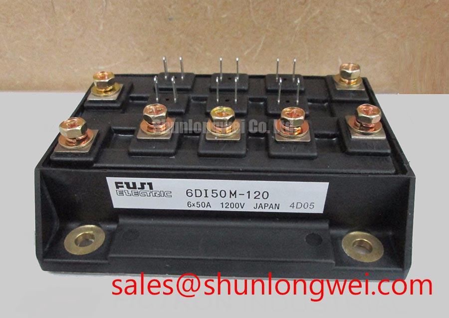
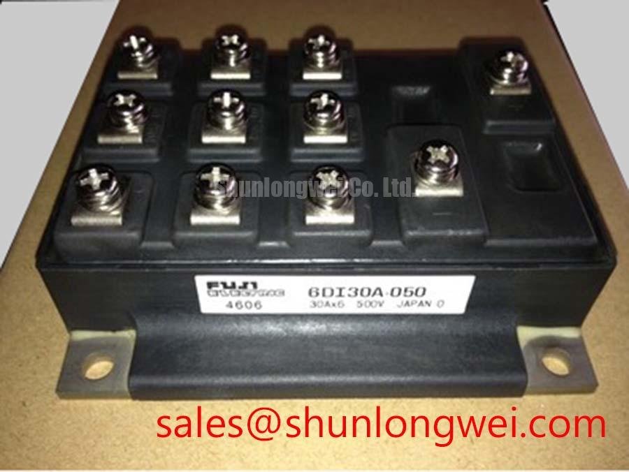
With power removed and the DC link discharged, first inspect the 6DI50M-050 terminal hardware, insulation surfaces, and cold resistance paths for signs of loose connections, contamination, or an abnormal collector to emitter reading before connecting a replacement module. This Fuji Electric power transistor Darlington module is officially rated at VCBO 500 V, VCEO(SUS) 450 V, IC 50 A, and ICP 100 A for a 1 ms pulse. These ratings provide the electrical identity that must be matched to the original inverter circuit before any repair decision.
| Official Specification | Rating | Integration Relevance |
|---|---|---|
| Collector Base Voltage | 500 V | Official Datasheet Specification for blocking voltage evaluation. |
| Collector Emitter Sustaining Voltage | 450 V | Official Datasheet Specification for switching under inductive load conditions. |
| Continuous Collector Current | 50 A | Official Datasheet Specification for continuous conduction assessment. |
| Peak Collector Current | 100 A, 1 ms | Official Datasheet Specification for short transient loading. |
| DC Current Gain | 100 typical | Official Datasheet Specification relevant to base drive demand. |
| Collector Power Dissipation | 200 W per element | Official Datasheet Specification for thermal assessment. |
| Isolation Voltage | 2500 V AC for 1 minute | Official Datasheet Specification between power and insulated structure. |
Do not assume that a Kelvin emitter terminal is available on every installed assembly. The system integrator should verify the original terminal drawing and drive board connection before assigning any auxiliary return path. Where the surrounding converter design provides a separate low current driver return, it should be routed apart from the main collector and emitter current loop. This is a Design Consideration intended to reduce shared inductive voltage during switching, which can otherwise disturb the drive reference and appear as irregular gate behaviour.
On a stopped commercial string inverter or micro grid energy storage converter, trace the driver return from the control board to the original module location and compare it with the high current emitter path. A damaged connector, lifted copper land, or incorrectly shared return may contribute to unstable switching, but waveform capture against a known good phase is required before attributing a fault to one cause. Keep the DC link loop compact to suppress turn off overshoot, then validate peak voltage against the actual DC link condition during switching tests.
A MOV and DC link capacitor network can limit system overvoltage stress only when its placement, lead length, and energy capability suit the converter. The behavior of capacitors under ripple current is relevant when reviewing the DC link network; see Film Capacitors in High Ripple Current DC Link Applications. For gate drive review methods, the linked Precision Gate Drive Design resource provides related circuit level context.
6DI50M-050 Circuit Protection & Reliability: Calibrating Thermal Time Constants and Peak Junction
The 200 W per element collector power dissipation rating is an Official Datasheet Specification, not a direct permission to run a module at that loss in every heatsink arrangement. During pulsed overload investigation, engineers should use the applicable manufacturer transient thermal data and the converter duty cycle to estimate junction response through the thermal impedance model. Peak junction margin depends on pulse width, repetition rate, case temperature, airflow, and the real clamping condition of the mounting interface.
The 100 A, 1 ms peak collector current rating should be treated as a defined pulse capability, not as a continuous current target. If startup or fault capture reveals repeated current peaks, inspect current sensing, phase commutation, motor cable condition, and DC link ripple together. Long motor cables can produce reflected voltage stress at the motor end, while the switching loop can see a separate turn off overshoot mechanism. Filtering and protection selection remain system determined and require measured waveforms.
⚠️ Field Alert: Tighten mounting hardware in a gradual cross pattern and use a thin, uniform thermal interface layer rather than allowing paste buildup at one side of the module.
Assembly Integrity & Layout Architecture: Implementing Thermal Interface Material Thickness Uniformity for 6DI50M-050
Before mounting the replacement, clean the heatsink contact face and check it for burrs, embedded debris, corrosion, or visible unevenness. As a General Industry Design Consideration, a controlled thermal interface material layer in the 50 to 100 μm range is often evaluated for flat, properly prepared power module mounting surfaces. It is not an official thickness specification for the 6DI50M-050. The final interface process must match the heatsink flatness, interface material data, clamping hardware, and the original equipment procedure.
Apply the interface material evenly, position the module without sliding it through a heavy paste ridge, then bring each mounting point down progressively in a cross sequence. This helps avoid localized tilt and trapped voids that can impair heat transfer. Verify terminal fastening separately from base mounting because a mechanically secure base does not confirm a sound power terminal connection.
For a circuit requiring a different voltage class or topology, a cross model review must include terminal layout, drive method, isolation arrangement, cooling interface, and protection coordination. The 7MBR50SA120-50 is a separate power module reference for engineering comparison, not an automatic replacement for this Darlington module.
Assembly Integrity & Layout Architecture: Implementing Optocoupler vs Digital Coreless Transformer for 6DI50M-050
Isolation in the 6DI50M-050 itself is officially specified at 2500 V AC for 1 minute. That value identifies the module isolation rating and does not establish the reinforced isolation rating, common mode transient immunity, or compliance status of the complete gate drive assembly. When selecting an optocoupler or digital isolator approach, designers should verify the required working voltage, isolation coordination, transient behavior, creepage, clearance, and safety documentation for the full converter.
A spurious command can arise from several locations, including driver supply disturbance, an incorrect return path, noise coupling at the controller interface, or unsuitable protection timing. Inspect the isolated driver supply and command waveform while comparing it with the power stage current and collector voltage. The principles behind dielectric withstand testing are described in Dielectric Strength and High Voltage Breakdown Testing, but final test conditions must follow the equipment requirements.
Where the converter includes an associated rectifier or power stage, the 3MBI50SX-120-02 can be reviewed as a separate topology component reference. Confirm each device’s voltage rating, current path, drive architecture, and mechanical interface from the original equipment documentation before installation.